Particle-collecting device and vehicle equipped with such a device

a technology of particle collection and collection device, which is applied in the direction of dispersed particle separation, mechanical equipment, separation processes, etc., can solve the problems of releasing particles into the atmosphere, affecting the safety of people, etc., and achieves the effects of small size, low maintenance cost and low energy consumption

Pending Publication Date: 2021-11-11
ALSTOM TRANSPORT TECH SAS +2
View PDF1 Cites 0 Cited by
  • Summary
  • Abstract
  • Description
  • Claims
  • Application Information

AI Technical Summary

Benefits of technology

[0008]There is therefore a need for a system to collect particles suspended in the atmosphere, intended to be installed in a vehicle, which is capable of collecting particles of very small size while requiring little maintenance and consuming little energy.

Problems solved by technology

Furthermore, the braking systems used in these vehicles frequently employ the friction of two parts against one another to dissipate the kinetic energy of the vehicle.
Friction is thus also the cause of the release of particles into the atmosphere.
The presence of such particles in the atmosphere is likely to induce a large number of illnesses among the people who inhale those particles.
Very fine particles may penetrate quite deeply into the lungs and cause numerous illnesses there.
In particular, very fine particles of the sizes PM 10 or PM 2.5, meaning that they have a diameter of less than or equal to 10 micrometers (μm) or 2.5 μm respectively, are difficult to trap in filters, because filters that can retain such small particles tend to clog easily.
Regular maintenance is therefore necessary to keep the filter effective over time, which is difficult when the filter is part of a device embedded in a vehicle.
Furthermore, the passage of air through filters that have meshes of very small size leads to significant pressure drops, and the effectiveness of the suction is therefore limited.
This phenomenon is even more significant when the filter is partially clogged, which happens very quickly due to the small size of the meshes.
However, even a new, clean filter poses a non-negligible obstacle to the passage of air.
A very-small-particle-collecting system using a filter therefore consumes a lot of energy.
When the particle-collecting device is embedded within a vehicle, this becomes problematic because the quantity of energy available is limited.

Method used


Image

  • Particle-collecting device and vehicle equipped with such a device
  • Particle-collecting device and vehicle equipped with such a device
  • Particle-collecting device and vehicle equipped with such a device

Examples


Embodiment Construction

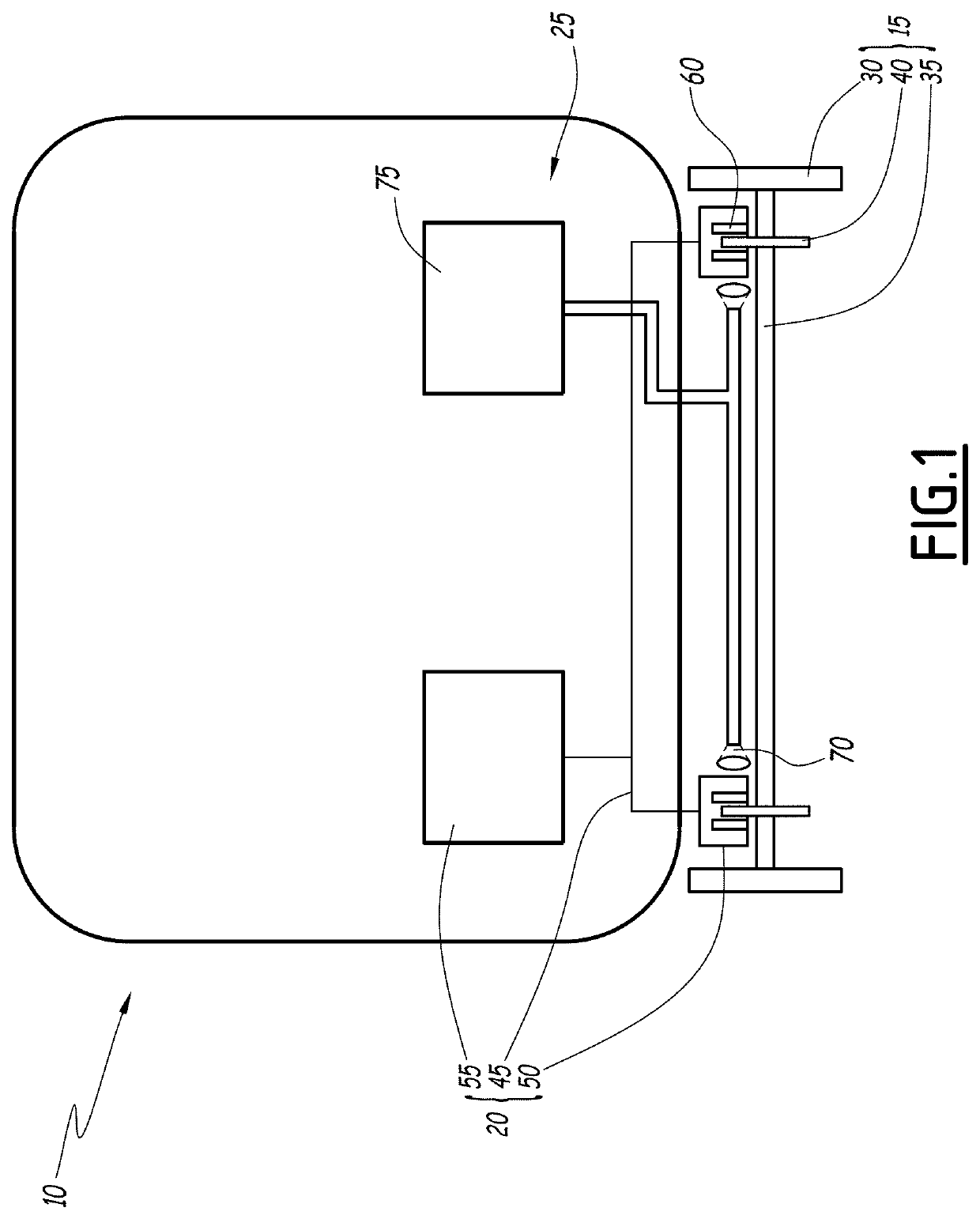
[0025]A vehicle 10 is schematically depicted in FIG. 1.

[0026]The vehicle 10 is, for instance, a mass transit vehicle, in particular a railway vehicle such as a train, tram, subway, or a car forming part of such a train, tram, or subway. In one variant, the vehicle 10 is a land vehicle such as a bus or trolleybus, or a personal vehicle.

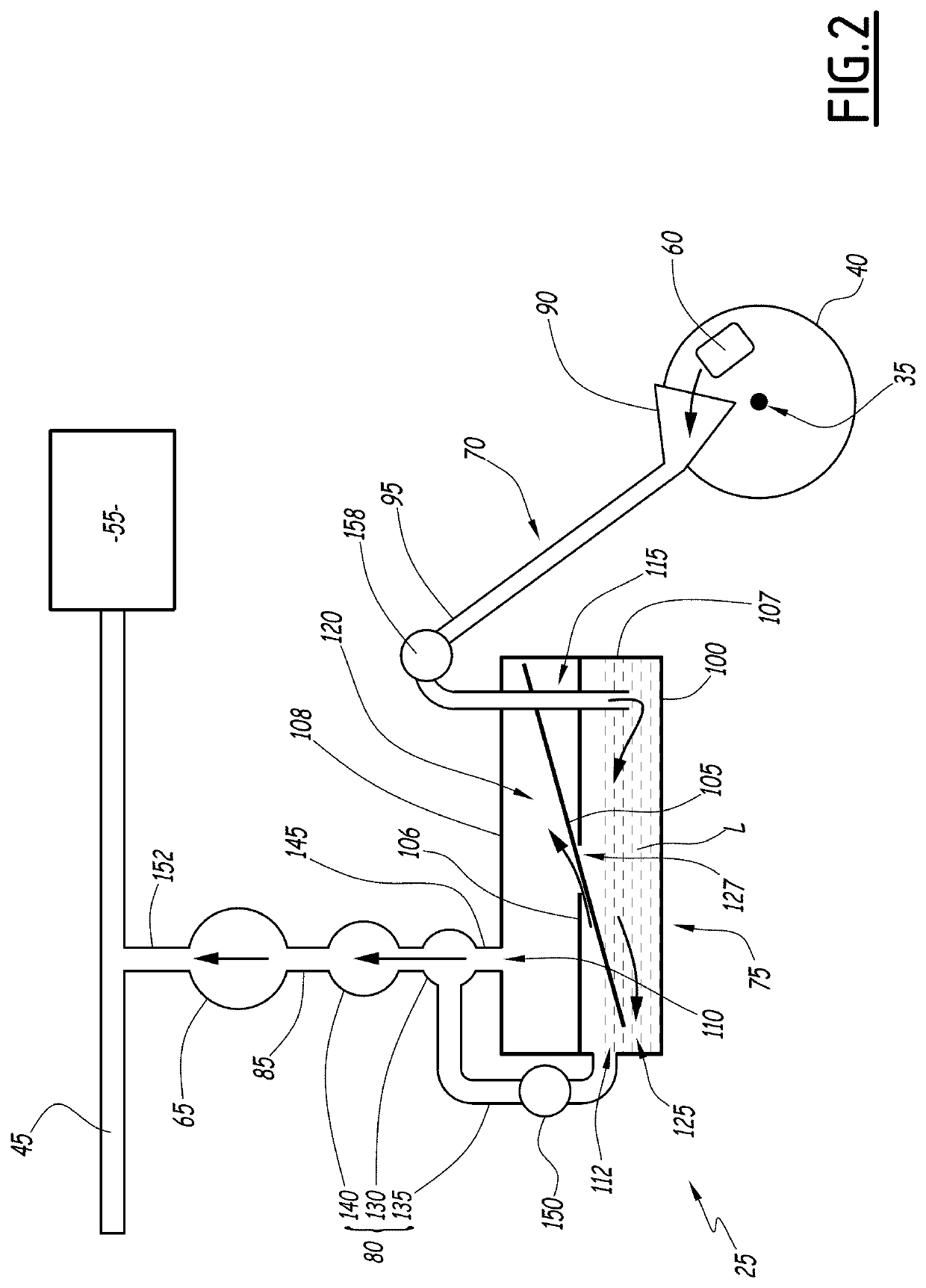
[0027]The vehicle 10 comprises at least one axle 15, a braking system 20, and a collection device 25.

[0028]In a manner known per se, each axle 15 comprises at least two wheels 30 connected by a shaft 35, at least one disc 40, also called a brake disc, for example two discs 40, being mounted on the shaft 35.

[0029]Each disc 40 is rigidly connected to the corresponding shaft 35.

[0030]The braking system 20 comprises a pneumatic circuit 45 and at least one brake 50, particularly a brake 50 for each of the discs 40.

[0031]The pneumatic circuit 45 is configured to control braking of the vehicle 10 by the brake(s) 50. In particular, the pneumatic circuit 45 is ...


PUM

PropertyMeasurementUnit
areaaaaaaaaaaa
areaaaaaaaaaaa
diameteraaaaaaaaaa

Abstract

A device includes a collection channel, a protection channel, and a tank containing a liquid. The collection channel is configured to direct an airflow containing particles from the outside to the interior of the tank. The airflow passes through the liquid and the protection channel, and is connected to an outlet of the tank. The tank includes a barrier configured to prevent liquid spatters from reaching the outlet and to allow the airflow to pass through the tank to the outlet. The protection channel is connected to a source of suction, is configured to direct the flow from the outlet to the source of suction. The protection channel includes a condenser configured to condense a vapor of the liquid and to direct the generated condensate to the tank.

Description

CROSS-REFERENCE TO RELATED APPLICATION[0001]This application claims priority to French Patent Application No. 20 04548 filed on May 7, 2020, the disclosure of which including the specification, the drawings, and the claims is hereby incorporated by reference in its entirety.FIELD OF THE INVENTION[0002]The present invention relates to a device for collecting particles suspended in the atmosphere, intended to equip a vehicle. The present invention also relates to a vehicle comprising such a collecting device.BACKGROUND OF THE INVENTION[0003]The operation of numerous types of vehicles involves the emission or release of particles of various sizes into the atmosphere. For instance, the exhaust gases of certain engines comprise solid particles resulting from the combustion of a fuel. Furthermore, the braking systems used in these vehicles frequently employ the friction of two parts against one another to dissipate the kinetic energy of the vehicle. Friction is thus also the cause of the ...

Claims


Application Information

Patent Timeline
Patent Type & Authority Applications(United States)
IPC IPC(8): B01D47/02B01D53/92
CPCB01D47/021B01D53/92B01D2247/14B01D2247/10F16D65/0031
Inventor OCTAU, CHARLÈNE ALINE FRANÇOISEMERESSE, DAMIEN LAURENT HENRIWATREMEZ, MICHEL
Owner ALSTOM TRANSPORT TECH SAS
Why Eureka
Try Eureka