Method of machining a component

a technology of machining and components, applied in the direction of computer control, program control, instruments, etc., can solve the problems of inconsistency between repairs, process manual drive and susceptible to variation, and component wear,

Pending Publication Date: 2021-11-11
ROLLS ROYCE PLC
View PDF5 Cites 0 Cited by
  • Summary
  • Abstract
  • Description
  • Claims
  • Application Information

AI Technical Summary

Problems solved by technology

Thus, maintenance and repair of components, which may be damaged during operation of the machine, are important in the continued operation of the machine.
Gas turbine components can be subject to wear, impact, handling damage, corrosion and/or cracking.
These may occur throughout the operational life of the component, or can occur due to manufacturing issues.
Thus, the process is manually driven and susceptible to variation dependent on the skill of the operator.
This results in inconsistency between repairs (i.e. the repairs are not repeatable).
As repairs are judged visual

Method used


Image

  • Method of machining a component
  • Method of machining a component
  • Method of machining a component

Examples


Embodiment Construction

[0048]Aspects and embodiments of the present disclosure will now be discussed with reference to the accompanying figures. Further aspects and embodiments will be apparent to those skilled in the art.

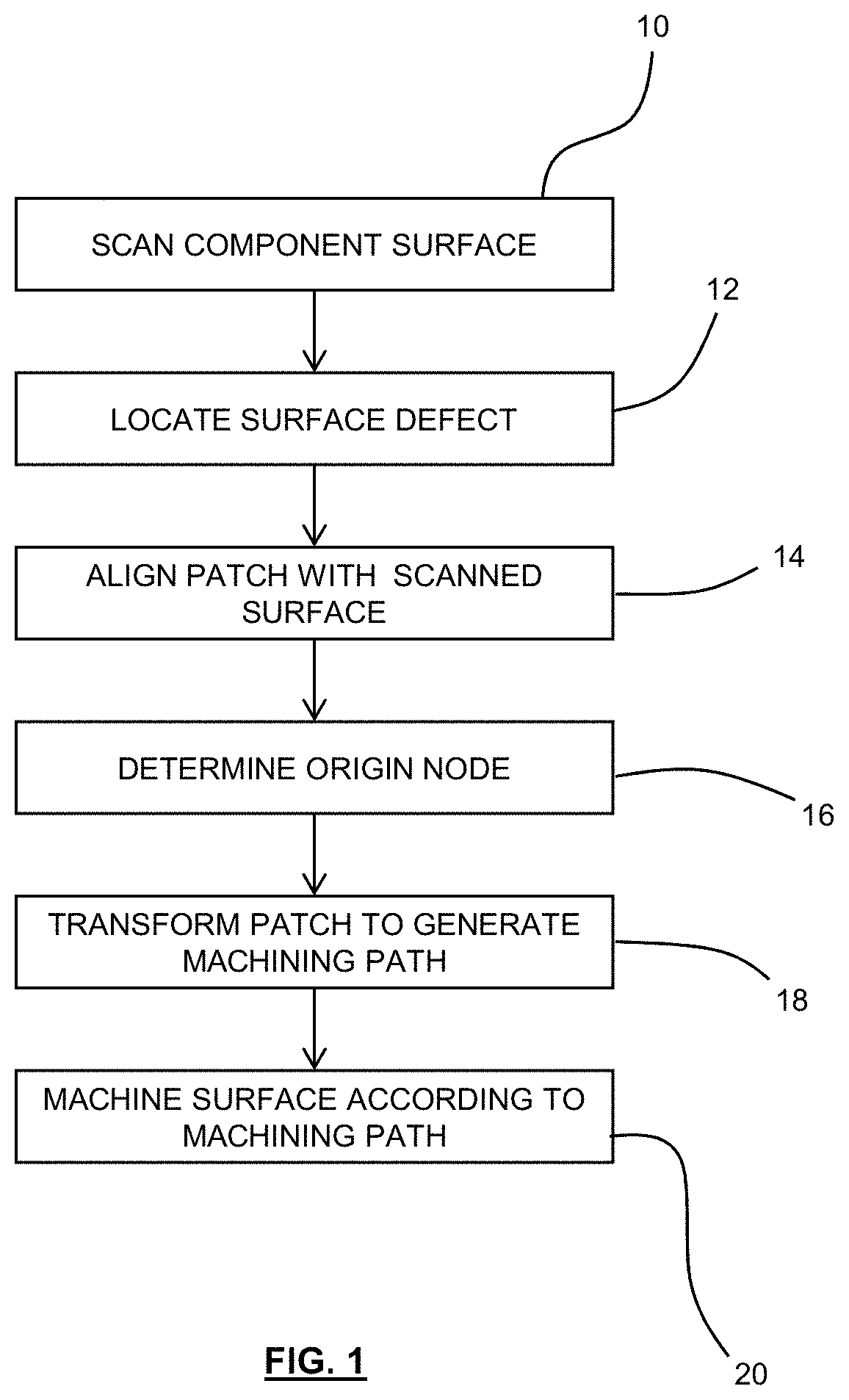
FIG. 1 provides an overview of a method for repairing a surface of a component having a surface defect.

[0049]The method comprises, at step 10, scanning the surface to obtain scanned electronic 3D data representing the scanned surface of the component (e.g. a CAD file representing the surface). In some cases, the surface may be scanned as part of a scan of the entire component. Any suitable scanning method may be used, including e.g. laser scanning and CT scanning.

[0050]At step 12, a surface defect is located on the scanned surface. This may be performed by inspecting the scanned surface (i.e. the 3D data representing the scanned surface) for the surface defect. The inspection may comprise identifying regions on the scanned surface that have a curvature above a threshold curvature (which ...


PUM

PropertyMeasurementUnit
Sizeaaaaaaaaaa
Areaaaaaaaaaaa
Distanceaaaaaaaaaa

Abstract

A method of machining a surface of a component. The method comprises scanning the surface of the component to obtain scanned electronic 3D data representing the scanned surface of the component locating a surface defect of the scanned surface and identifying a defect region that surrounds and includes the surface defect, and providing electronic 3D data representing a patch having the desired shape of the defect region. The method also comprises transforming the patch to generate a tooling path for repairing the surface defect. The transformation comprising translating a plurality of nodes of the patch. The translation distance of each node based on the distance of that node from an origin node of the patch. The method further comprises machining the surface of the component according to the generated tooling path.

Description

CROSS-REFERENCE TO RELATED APPLICATIONS[0001]This specification is based upon and claims the benefit of priority from UK Patent Application Number GB2006769.0 filed on 7 May 2020, the entire contents of which are incorporated herein by reference.BACKGROUNDTechnical Field[0002]The present disclosure provides a method of machining a surface of a component as set out in the appended claims. In particular, the method may form part of a process for repairing or finishing of a component such as an aerofoil (e.g. a turbine or compressor blade for a gas turbine engine).Description of the Related Art[0003]Machines often rely on the integrity of their components in order to operate in an efficient and safe manner. Thus, maintenance and repair of components, which may be damaged during operation of the machine, are important in the continued operation of the machine.[0004]For example, gas turbine engines comprise a number of precision-engineered components, the geometry of which must be mainta...

Claims


Application Information

Patent Timeline
IPC IPC(8): B24B51/00B24B7/10
CPCB24B51/00G05B15/02B24B7/10F01D5/005B23P6/002G05B19/4099G05B2219/37047G05B2219/32228G05B2219/45147G05B19/4097G05B19/4207F05D2270/8041F05D2260/81
Inventor HUCKERBY, KARL S.
Owner ROLLS ROYCE PLC
Why Eureka
Try Eureka