This helps you quickly interpret patents by identifying the three key elements:
Problems solved by technology
Method used
Benefits of technology
Benefits of technology
The present invention provides a nozzle structure for fuel injection systems for combustion engines that can consistently break up fuel into droplets of a desired size, distribution, and pattern. This can improve the combustion characteristics of the fuel, reducing emissions, improving fuel economy, and reducing build-up of byproducts within the engine. The size of the fuel droplets can also affect the depth of penetration of the fuel from the nozzle into the combustion chamber, which can lead to more efficient mixing of the fuel with the air charge. The nozzle structure can provide a repeatable spray pattern and can control the droplet size and pattern, resulting in improved engine performance. The addition of a counterbore to the through-holes or ports of the nozzle structure can further control the droplet size distribution and spray pattern.
Problems solved by technology
Some fuel injector nozzles fail to provide a fuel spray that breaks up into a desired droplet pattern or plume at an optimum distance from the nozzle.
A poorly designed fuel spray pattern or plume and variations in breakup distance can lead to incomplete combustion, which in turn leads to higher emissions, lower fuel economy, and the build-up of combustion byproducts (e.g., coking) within the combustion chamber of the engine.
Method used
Image
Click on the blue label to locate the original text in one second.
Reading with bidirectional positioning of images and text.
Examples
embodiment 1
[0129]2. The nozzle or 1a, wherein the upstream end of the initial section (e.g., in one embodiment, the inlet opening of the through-hole) has a cross-sectional shape with a minor axis length and a major axis length (e.g., an oval shape, rod shape, rectangular shape, elliptical shape, star shaped, etc.).
embodiment 2
[0130]3. The nozzle , wherein the ratio of the major axis length to the minor axis length of the upstream end of the initial section (e.g., in one embodiment, the inlet opening of the through-hole) is at least 2:1 or greater (e.g., at least 2.5:1, 3:1, 3.5:1, 4:1, 4.5:1, 5:1, 5.5:1, 6:1, 6.5:1, 7:1, 7.5:1, 8:1, 8.5:1, 9:1, 9.5:1, 10:1, or even higher).
[0131]4. The nozzle according to embodiment 1 or 1a, wherein the upstream end of the initial section (e.g., in one embodiment, the inlet opening of the through-hole) has a circular cross-sectional shape.
[0132]5. The nozzle according to any one of embodiments 1, 1a and 1b to 4, wherein the downstream end of the initial section has a cross-sectional shape with a minor axis length and a major axis length (e.g., an oval shape, rod shape, rectangular shape, elliptical shape, star shaped, etc.).
embodiment 5
[0133]6. The nozzle , wherein the ratio of the major axis length to the minor axis length of the downstream end of the initial section is at least 2:1 or greater (e.g., at least 2.5:1, 3:1, 3.5:1, 4:1, 4.5:1, 5:1, 5.5:1, 6:1, 6.5:1, 7:1, 7.5:1, 8:1, 8.5:1, 9:1, 9.5:1, 10:1, or even higher).
[0134]7. The nozzle according to embodiment 5 or 6, wherein the cross-sectional shape at the downstream end of the initial section is crescent-shaped and includes a concave (e.g., circular) side opposite a convex (e.g., circular) side along its major axis length (see, e.g., FIGS. 24, 26, 27, 31 and 33).
PUM
Abstract
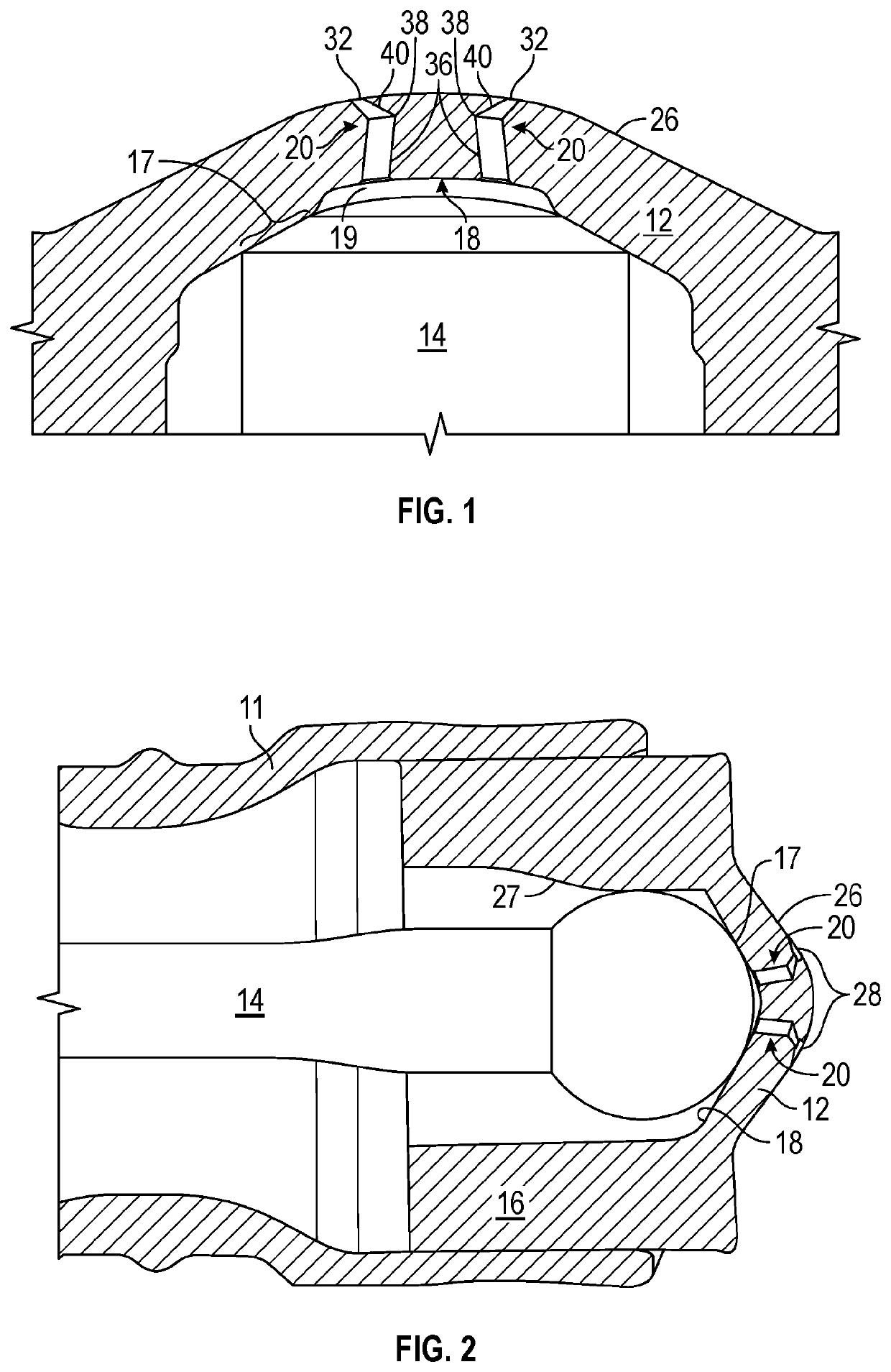
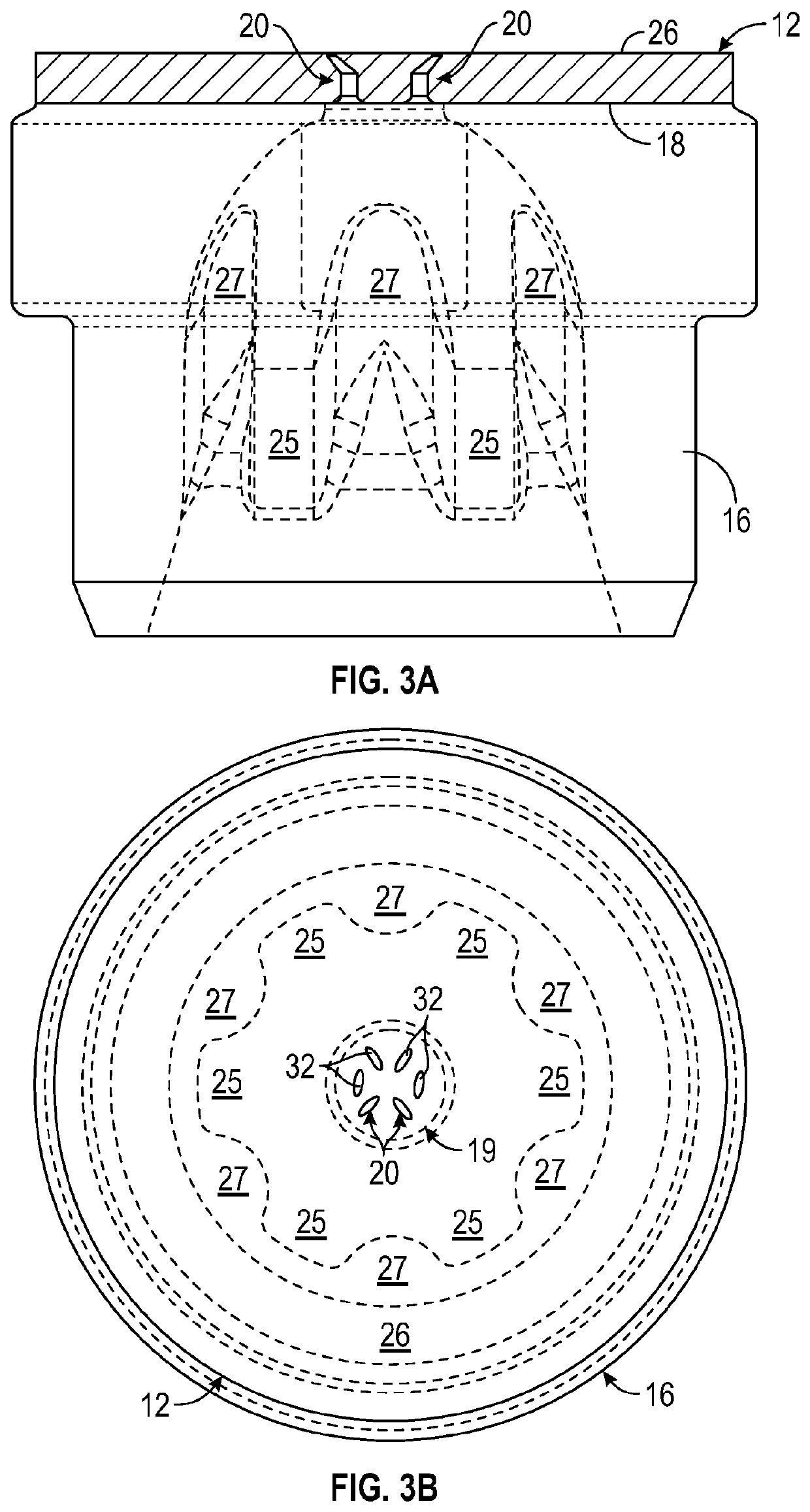
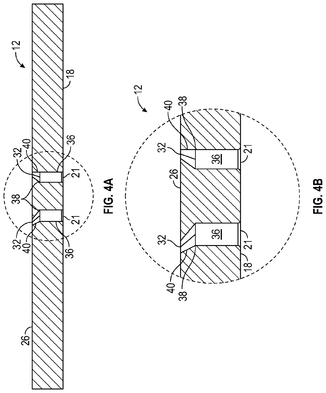
A nozzle (10) comprising a through-hole (20) having an optional initial section (36) in fluid communication with the inlet opening (21) of the through-hole (20), a fluid shearing section (40) in fluid communication with the outlet opening (32) of the through-hole (20), and an optional transition region (38) in fluid communication with the initial section (36) and the fluid shearing section (40). The initial section (36) has a relatively constant cross-sectional shape along at least a 20% portion of its length, a shape that converges to the transition region (38), or both. The transition region (38) is disposed along the through-hole length, with a relatively uniform, diverging, converging, diverging and converging, or converging and diverging cross-sectional area along its length. The fluid shearing section (40) has an upstream end in fluid communication with the transition region (38), and a diverging cross-sectional shape along at least a 20% portion of its length that has a minor axis length and a major axis length.
Description
[0001]The present invention relates to nozzles (e.g., fuel injector nozzles), in particular to nozzles that include a nozzle structure or component (e.g., a nozzle plate, a monolithic nozzle plate and valve guide, or an assembled nozzle plate and valve guide) having one or more microstructured through-holes or ports, more particularly to a nozzle structure or component having one or more through-holes or ports that include an optional transition region disposed in fluid communication between an optional initial section and a fluid shearing section, methods of making the same, and methods of using the same.BACKGROUND[0002]The background description provided here is for the purpose of generally presenting the context of the disclosure. Work of the presently named inventors, to the extent it is described in this background section, as well as aspects of the description that may not otherwise qualify as prior art at the time of filing, are neither expressly nor impliedly admitted as pri...
Claims
Application Information
Patent Timeline
Application Date:The date an application was filed.
Publication Date:The date a patent or application was officially published.
First Publication Date:The earliest publication date of a patent with the same application number.
Issue Date:Publication date of the patent grant document.
PCT Entry Date:The Entry date of PCT National Phase.
Estimated Expiry Date:The statutory expiry date of a patent right according to the Patent Law, and it is the longest term of protection that the patent right can achieve without the termination of the patent right due to other reasons(Term extension factor has been taken into account ).
Invalid Date:Actual expiry date is based on effective date or publication date of legal transaction data of invalid patent.

