Combustion controller for compression-ignition direct-injection engine and engine control system for the same

Active Publication Date: 2008-10-02
DENSO CORP
View PDF16 Cites 61 Cited by
  • Summary
  • Abstract
  • Description
  • Claims
  • Application Information

AI Technical Summary

Benefits of technology

[0014]The present invention has been made in consideration of the above situation, and provides a compression-ignition direct-injection engine combustion controller and an engine control system capable of

Problems solved by technology

Accordingly, in multistep injection control, an error (shift) easily occurs in the combustion characteristic of the main combustion.
When such error occurs in the combustion characteristic, emission deterioration and unstable combustion status are conceivable.
Accordingly, when fuel with extremely low cetane number is used, it is impossible to obtain a sufficient combustion amount (heat generation rate) and a sufficient torque.
This may cause emission deterioration (white smoke or the like due to increased HC generation amount) and/or degradation of drivability, and at worst, an accidental fire.
However, even when the above-des

Method used


Image

  • Combustion controller for compression-ignition direct-injection engine and engine control system for the same
  • Combustion controller for compression-ignition direct-injection engine and engine control system for the same
  • Combustion controller for compression-ignition direct-injection engine and engine control system for the same

Examples


Example

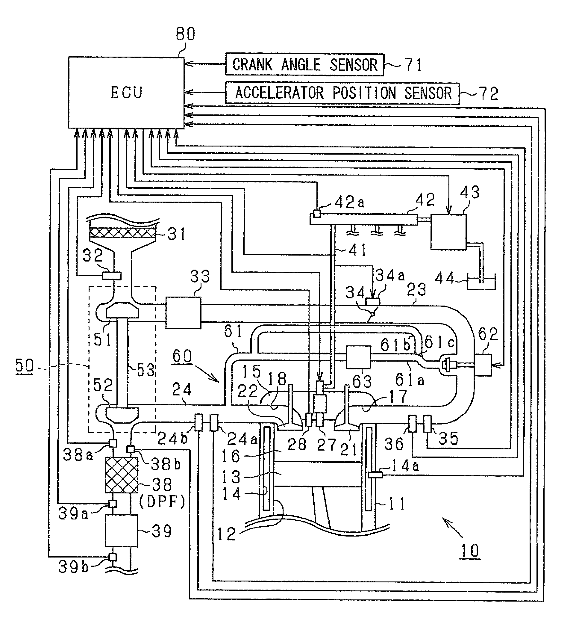
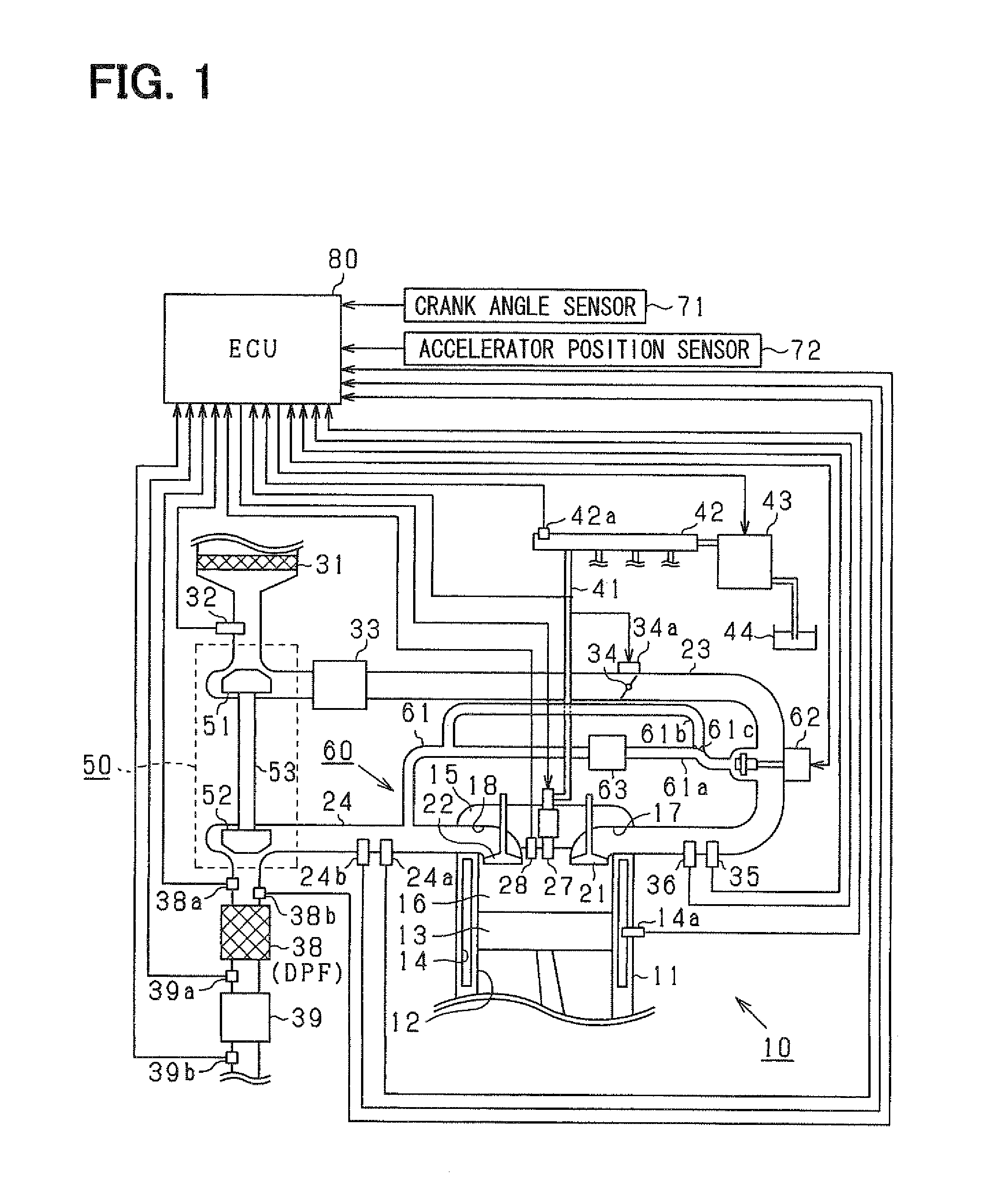
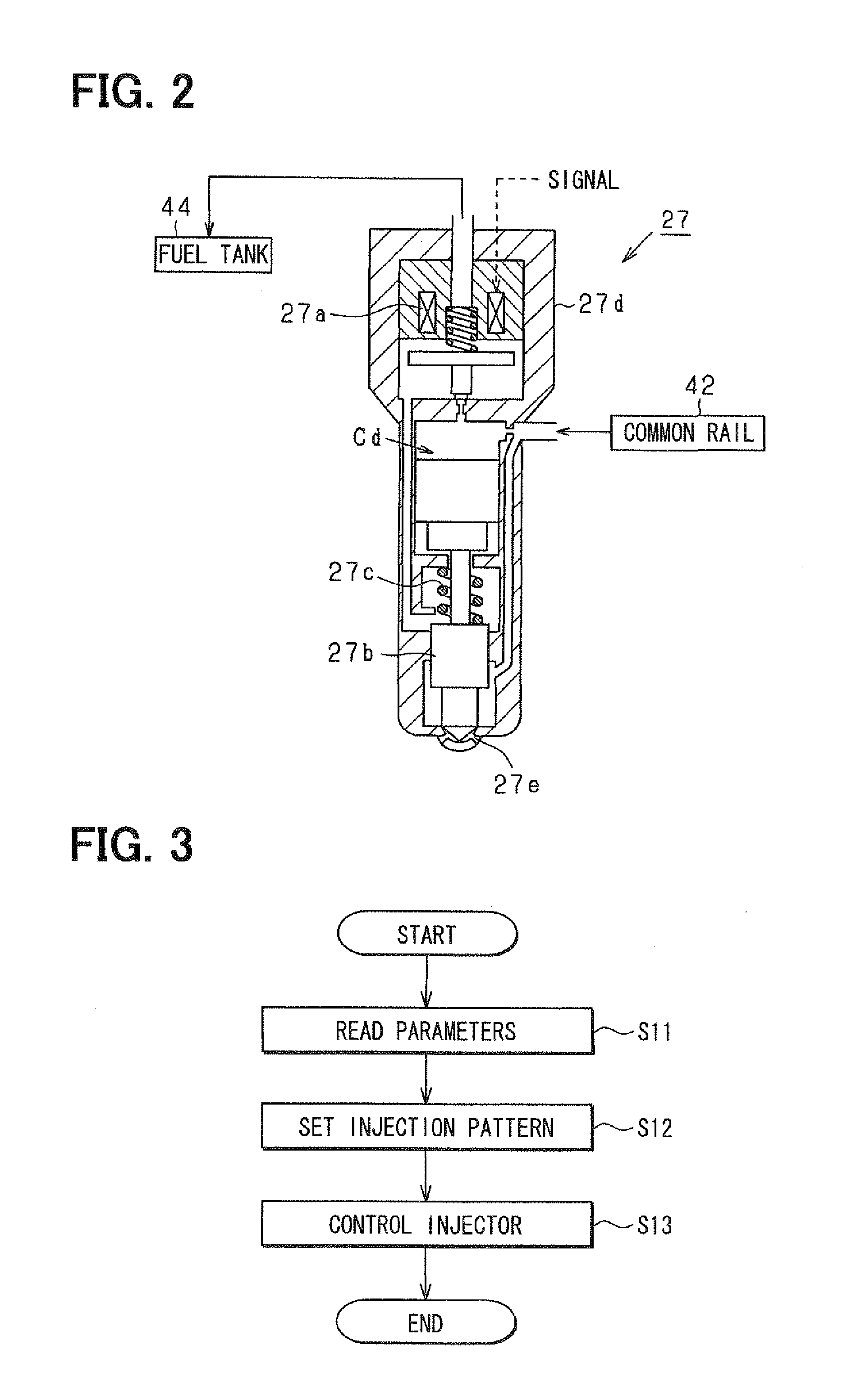
[0078]Hereinbelow, a first embodiment in which a compression-ignition direct-injection engine combustion controller and an engine control system according to the present invention are embodied will be described with reference to FIGS. 1 to 3, 4A to 4E, 5, FIGS. 6A and 6B, and FIGS. 7 to 9, Note that the engine control system according to the present embodiment is a common-rail fuel-injection control system (high-pressure fuel supply system) to control a compression-ignition diesel engine (internal combustion engine) as a vehicle power source. In this system, as in the case of the system disclosed in the above JP-2004-100559A, high pressure fuel (e.g., light oil at “1000 atm” or higher injection pressure) is directly inject-supplied (direct-injection supplied) to a combustion chamber (a portion to conduct fuel combustion) in an engine cylinder.

[0079]A configuration of the engine control system according to the present embodiment will be schematically described with reference to FIG. ...

Example

Second Embodiment

[0144]Next, a second embodiment in which the compression-ignition direct-injection engine combustion controller and the engine control system according to the present invention are embodied will be described with reference to FIGS. 11A and 11B, and FIGS. 12 and 13. Note that the apparatus and the system according to the present embodiment basically have the same configuration according to the first embodiment as shown in FIG. 1. Accordingly, for the sake of convenience of explanation, the explanations of common constituent elements and operations will be omitted, and the difference from the above-described first embodiment will be mainly described.

[0145]As described above, when the time from the execution (start) of the main injection to the start of combustion (ignition) (main ignition delay time) is too long, sudden heat generation by combustion of a large amount of fuel at once, and inconvenience such as noise occurs. On the other hand, in a direct injection engi...

Example

Third Embodiment

[0162]Next, a third embodiment of the present invention will be described. The apparatus and the system according to the present embodiment basically have the same configuration according to the first embodiment as shown in FIG. 1. Accordingly for the sake of convenience of explanation, the explanations of common constituent elements and operations will be omitted.

[0163]In the present embodiment, ignition timing feedback control is performed so as to bring the actual ignition timing of the main injection into correspondence with target ignition timing. The injection timing of the main injection is controlled based on the deviation between the actual ignition timing of the main injection and the target ignition timing. In such ignition timing feedback control, when the ignition timing deviation of the main injection is equal to or greater than a predetermined value, or when the injection-timing feedback control amount calculated based on the ignition timing deviation ...


PUM


Abstract

As a compression-ignition direct-injection engine combustion controller, a program for detecting ignition timing of a main injection Mn (main ignition timing), a program for correcting a command value of main injection execution timing in a direction to the side where a detection value is converged within a predetermined range, a program for determining whether or not the corrected command value is within a predetermined range, and a program for, when it is determined that the command value is not within the range, correcting a command value related to an injection amount of a pilot injection Pt based on whether or not the command value is on a delay side or an advance side of the range.

Description

CROSS-REFERENCE TO RELATED APPLICATION[0001]This application is based on Japanese Paten Applications No. 2007-96862 filed on Apr. 2, 2007 and No. 2008-27571 filed on Feb. 7, 2008, the disclosures of which are incorporated herein by reference.FIELD OF THE INVENTION[0002]The present invention relates to a combustion controller for a compression-ignition direct-injection engine, applied to an engine system having a compression ignition engine and a fuel injection valve for direct injection, to control the operation of at least one actuator in the system. Further, the present invention relates to an engine control system including the compression-ignition direct-injection engine combustion controller.BACKGROUND OF THE INVENTION[0003]In an engine for a vehicle (particularly, internal combustion engine), fuel injected by a fuel injection valve (injector) is ignited and combusted within a combustion chamber in a predetermined cylinder, and torque (power) is generated on a predetermined out...

Claims


Application Information

Patent Timeline
IPC IPC(8): F02D45/00
CPCF02D35/025F02D35/028F02D41/403Y02T10/44F02D35/023Y02T10/40
Inventor KOJIMA, AKIKAZUHARAGUCHI, HIROSHIMORIMOTO, YOUHEIKURONITA, TOKUJISASAKI, SATORU
Owner DENSO CORP
Why Eureka
Try Eureka