
Semiconductor Device Structure with Uneven Gate Profile

Active Publication Date: 2021-11-18
TAIWAN SEMICON MFG CO LTD
View PDF3 Cites 0 Cited by
  • Summary
  • Abstract
  • Description
  • Claims
  • Application Information

AI Technical Summary

Benefits of technology

The patent text describes a new method for making a metal gate stack for a field-effect transistor (FET) in advanced technology nodes of the integrated circuit industry. The method addresses issues of proper gap filling and profile control, especially for FETs with 3D structure, and improves device performance and product yield. The technical effects of the method include improved gap filling, reduced contact resistance, and better threshold voltage control. The method also provides a new structure for the metal gate stack that addresses these issues.

Problems solved by technology

Due to high packing density and small feature sizes, it is challenging to achieve proper gap filling and profile control, especially for the FETs with 3D structure, such as 3D fin field effect transistors (FINFETs).
Furthermore, device performance and product yield are challenged.

Method used


Image

  • Semiconductor Device Structure with Uneven Gate Profile
  • Semiconductor Device Structure with Uneven Gate Profile
  • Semiconductor Device Structure with Uneven Gate Profile

Examples


Embodiment Construction

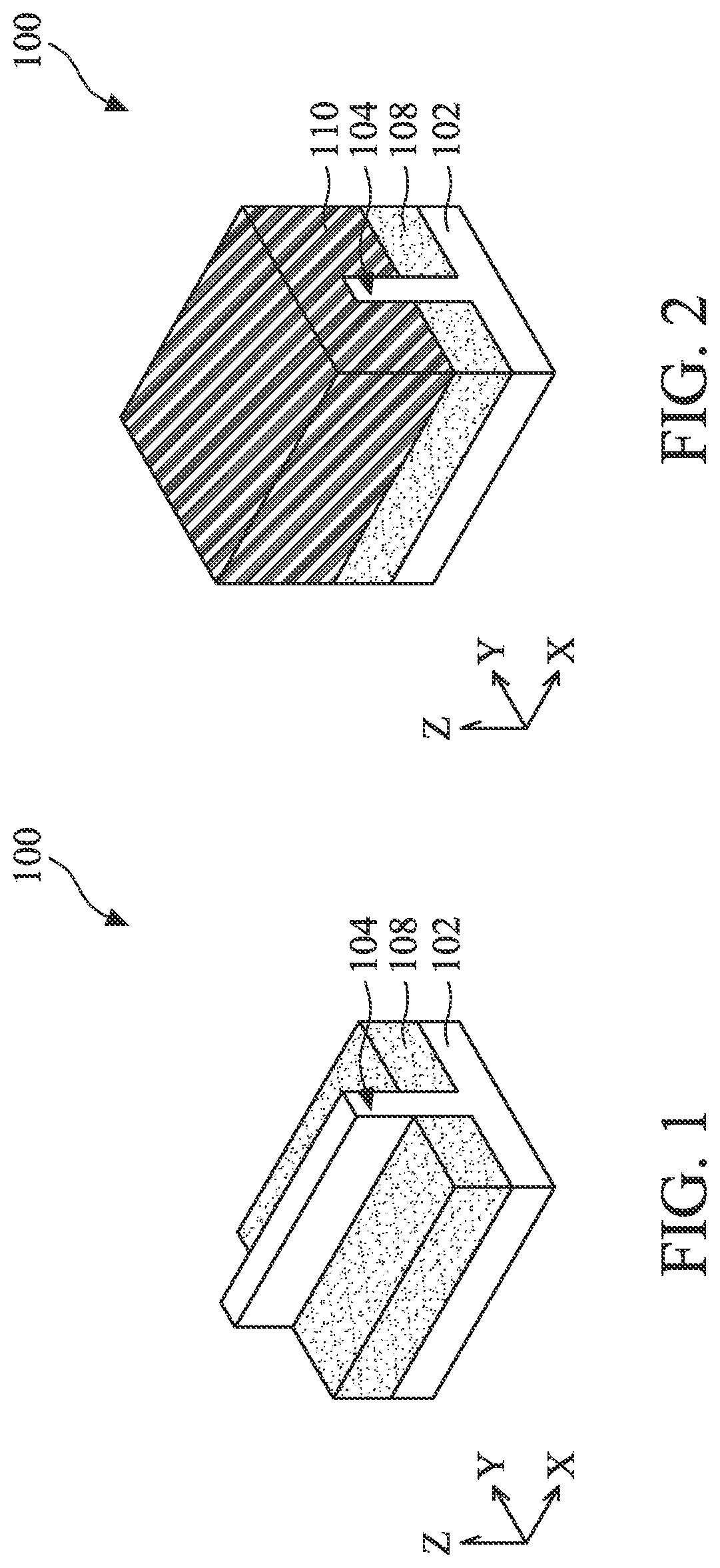
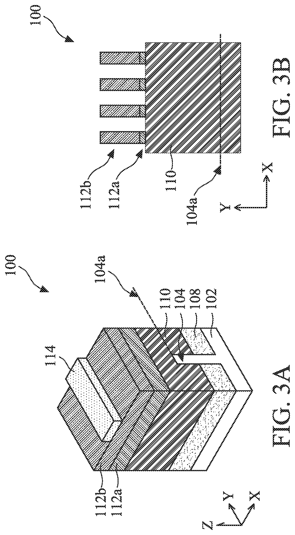
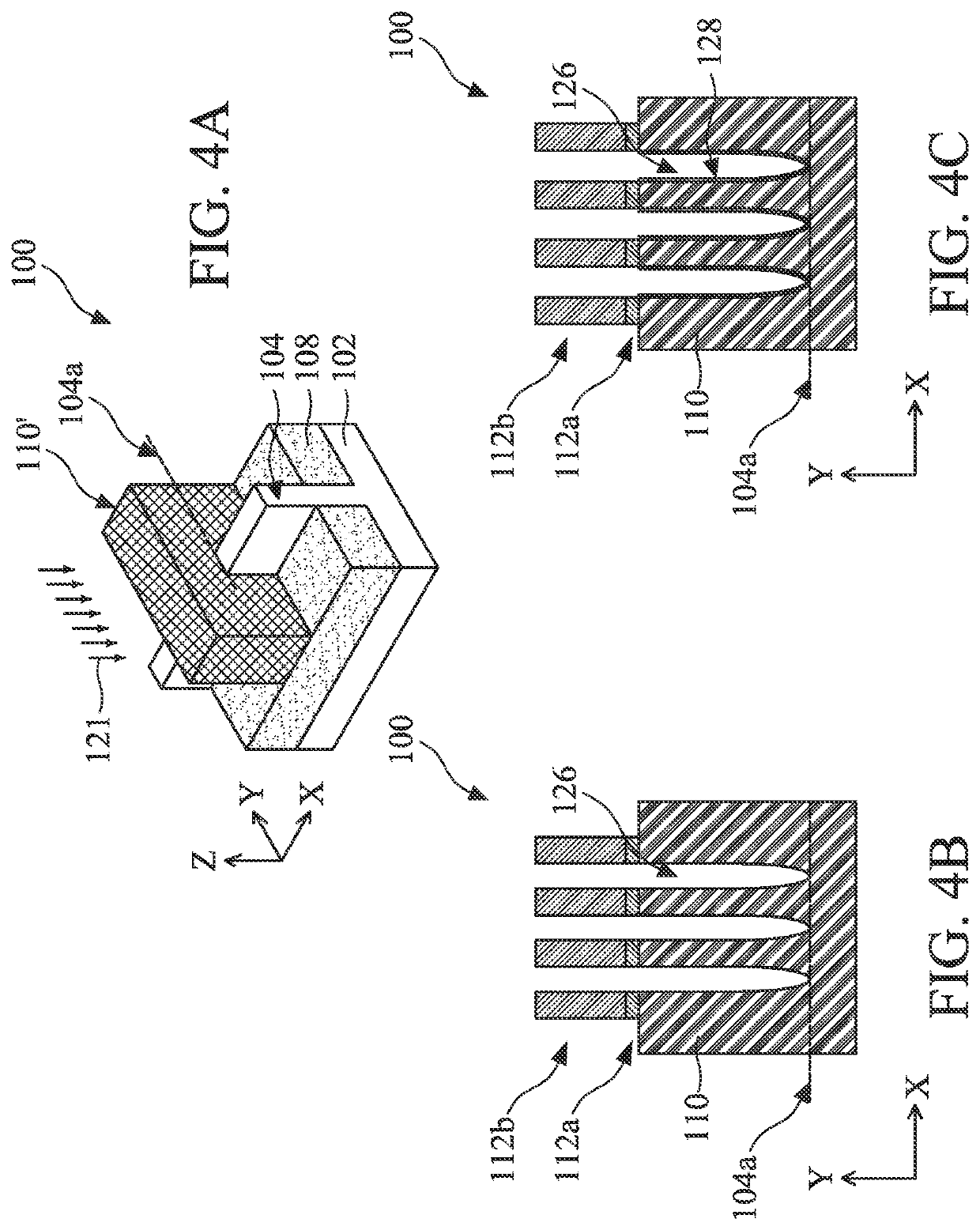
[0023]The following disclosure provides many different embodiments, or examples, for implementing different features of the provided subject matter. Specific examples of components and arrangements are described below to simplify the present disclosure. These are, of course, merely examples and are not intended to be limiting. For example, the formation of a first feature over or on a second feature in the description that follows may include embodiments in which the first and second features are formed in direct contact and may also include embodiments in which additional features may be formed between the first and second features, such that the first and second features may not be in direct contact. In addition, the present disclosure may repeat reference numerals and / or letters in the various examples. This repetition is for the purpose of simplicity and clarity and does not in itself dictate a relationship between the various embodiments and / or configurations discussed.

[0024]Fu...


PUM


Abstract

A semiconductor structure includes a semiconductor substrate; fin active regions protruded above the semiconductor substrate; and a gate stack disposed the fin active regions; wherein the gate stack includes a high-k dielectric material layer, and various metal layers disposed on the high-k dielectric material layer. The gate stack has an uneven profile in a sectional view with a first dimension D1 at a top surface, a second dimension D2 at a bottom surface, and a third dimension D3 at a location between the top surface and the bottom surface, and wherein each of D1 and D2 is greater than D3.

Description

PRIORITY DATA[0001]This application claims priority to U.S. Provisional Patent Application No. 62 / 704,570 filed on May 15, 2020, entitled “GATE STRUCTURE AND METHOD WITH ENHANCED GATE CONTACT AND THRESHOLD VOLTAGE” (Attorney Docket No. P2020-0572 / 24061.4204PV01), the entire disclosure of which is hereby incorporated herein by reference.BACKGROUND[0002]In advanced technology nodes of integrated circuit industry, high k dielectric material and metal are adopted to form a gate stack of a field-effect transistor (FET) such as a metal-oxide-semiconductor field-effect transistor (MOSFET). In existing methods to form the metal gate stack, metal gates are formed in a gate replacement process that removes dummy gates and fills in the gate trenches with gate materials. Due to high packing density and small feature sizes, it is challenging to achieve proper gap filling and profile control, especially for the FETs with 3D structure, such as 3D fin field effect transistors (FINFETs). Furthermore...

Claims


Application Information

Patent Timeline
IPC IPC(8): H01L29/423H01L27/092H01L29/78H01L29/66H01L21/8238H01L29/06H01L29/786H01L29/40
CPCH01L29/42376H01L27/0924H01L29/785H01L29/66795H01L21/823821H01L29/401H01L29/42392H01L29/0665H01L29/4236H01L29/78642H01L29/66742H01L21/82385H01L29/78696H01L27/0886H01L29/7856H01L29/4966H01L29/66545H01L21/823431H01L21/823437
Inventor LAI, CHI-SHENGPENG, YU-FANCHEN, LI-TINGLU, YU-SHANWU, YU-BEYSUN, WEI-CHUNGPENG, YUAN-CHINGKAO, KUEI-YULIN, SHIH-YAOLIN, CHIH-HANLIU, PEI-YIYAN, JING YI
Owner TAIWAN SEMICON MFG CO LTD
Learn More