
Multiaxis gyroscope with supplementary masses

a multi-axis, supplementary technology, applied in the field of microelectromechanical gyroscopes, can solve the problems of low sensitivity of the gyroscope, energy leakage from the drive mode, noisy output signal of such a gyroscope, etc., to improve vibration robustness and strong detection signals

Active Publication Date: 2021-11-25
MURATA MFG CO LTD
View PDF0 Cites 3 Cited by
  • Summary
  • Abstract
  • Description
  • Claims
  • Application Information

AI Technical Summary

Benefits of technology

The disclosure is about a way to use a system of four objects that move in a circle around a central point. Each object is connected to two other objects called elongated mass elements and synchronization bars. This arrangement has two advantages: it reduces interference between the objects and it improves the detection of signals from the objects because they move in different directions. This design also makes the system more robust against vibrations.

Problems solved by technology

A general problem in gyroscope design is that the oscillation of the proof masses in these two modes should preferably not be perturbed by external disturbances, for example vibrations in surrounding elements.
A simple MEMS gyroscope may be constructed utilizing only one oscillating proof mass, but the output signal of such a gyroscope will typically be very noisy when external vibrations are present at frequencies close to the operating frequency.
One-mass gyroscopes would be practical only at operating frequencies above 50 kHz, but in these frequencies the sensitivity of the gyroscope may be very low and other disturbing effects, such as quadrature signals arising from manufacturing imperfections, often become very prominent.
Also, the unbalanced drive mode of the single mass drive causes energy leakage from the drive mode due to reaction forces of the drive oscillation.
This will induce all kinds of issues; increase drive force needed for operation, stability issues and requirement for hard die attachment etc.
It is challenging to design multiaxis gyroscopes that are robust against external vibrations because the mass system needs multiple degrees of freedom in order to respond to rotation about any of the three perpendicular axes.

Method used


Image

  • Multiaxis gyroscope with supplementary masses
  • Multiaxis gyroscope with supplementary masses
  • Multiaxis gyroscope with supplementary masses

Examples


first embodiment

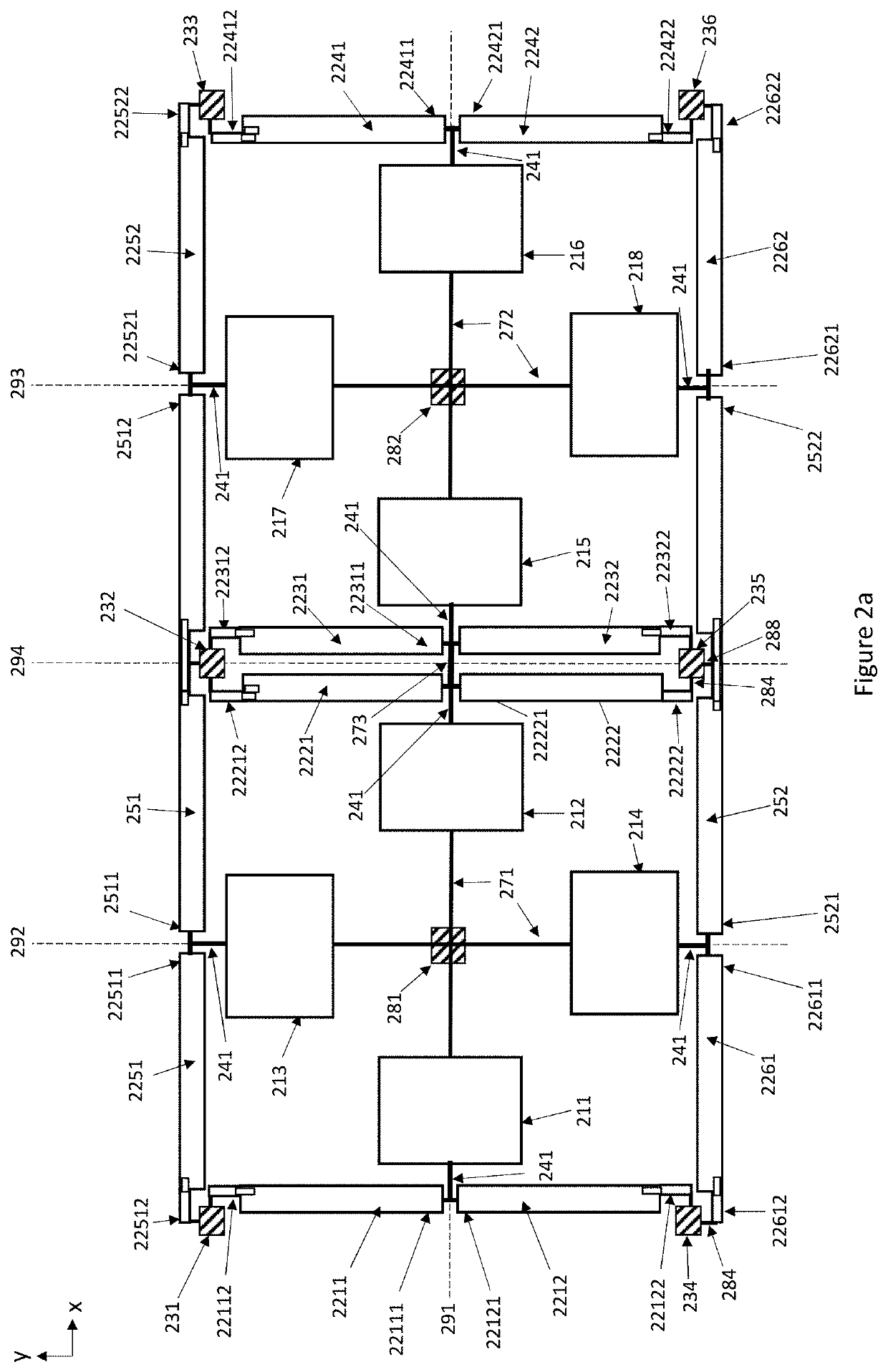
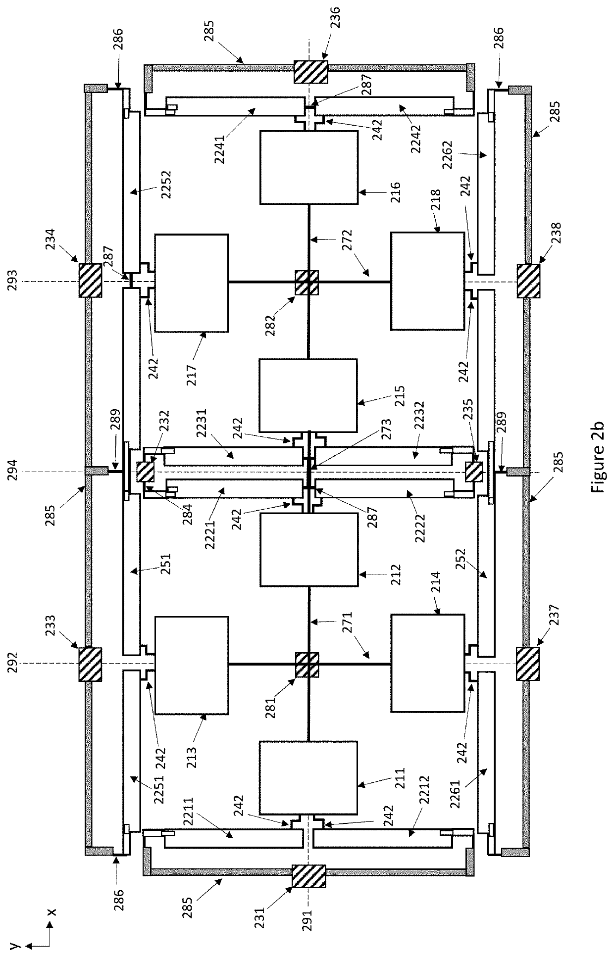
[0017]FIG. 2a illustrates a microelectromechanical gyroscope which comprises a first Coriolis mass quartet which in its rest position lies in a device plane. The gyroscope also comprises a first quartet center point where a lateral axis 291 crosses a first transversal axis 292 orthogonally in the device plane. The gyroscope comprises a first central anchor point 281 located at the first quartet center point.

[0018]The first Coriolis mass quartet comprises a first (211), second (212), third (213) and fourth (214) Coriolis mass which are in their rest positions symmetrically arranged around the first quartet center point so that the first (211) and second (212) Coriolis masses are aligned on the lateral axis 291 and the third (213) and fourth (214) Coriolis masses are aligned on the first transversal axis 292.

[0019]The gyroscope also comprises a second Coriolis mass quartet which in its rest position lies in the device plane and a second quartet center point where the lateral axis 291 ...

second embodiment

[0076]FIG. 4a illustrates a microelectromechanical gyroscope where the gyroscope comprises a Coriolis mass quartet which in its rest position lies in a device plane and a quartet center point where a lateral axis 491 crosses a transversal axis 492 orthogonally in the device plane. The gyroscope comprises a central anchor point 481 located at the quartet center point and the Coriolis mass quartet comprises four Coriolis masses 411−414 which are in their rest positions symmetrically arranged around the quartet center point. The first and second Coriolis masses (411, 412) in the Coriolis mass quartet are aligned on the lateral axis 491 in their rest position. The third and fourth Coriolis masses (413, 414) in the Coriolis mass quartet are aligned on the transversal axis 492 in their rest position.

[0077]The gyroscope further comprises a central suspension arrangement 475 for suspending the Coriolis mass quartet 411−414 from the central anchor point 481. The central suspension arrangemen...


PUM


Abstract

A gyroscope with a first Coriolis mass quartet and a second Coriolis mass quartet arranged around two quartet center points, and two elongated mass elements or synchronization bars aligned with each other outside of each Coriolis mass. One end of each elongated mass element and synchronization bar is attached to the corresponding Coriolis mass. Each elongated mass element is suspended from a peripheral anchor point by a mass element suspension arrangement which allows said elongated mass element to undergo rotational motion both in the device plane and out of the device plane. Each elongated synchronization bar is suspended from a peripheral anchor point by a synchronization bar suspension arrangement which allows said elongated synchronization bar to undergo rotational motion both in the device plane and out of the device plane substantially around its midpoint.

Description

FIELD OF THE DISCLOSURE[0001]This disclosure relates to microelectromechanical gyroscopes, and more particularly to gyroscopes where an oscillating mass system is used to measure angular rotation about multiple rotation axes.BACKGROUND OF THE DISCLOSURE[0002]In microelectromechanical (MEMS) gyroscopes, proof masses should preferably be easily set to oscillate in a primary oscillation mode (which may also be called the drive oscillation mode) and also easily undergo oscillation in a secondary oscillation mode (which may also be called the sense oscillation mode) induced by the Coriolis force. A general problem in gyroscope design is that the oscillation of the proof masses in these two modes should preferably not be perturbed by external disturbances, for example vibrations in surrounding elements. A gyroscope should preferably be unperturbed by both linear and rotational vibrations so that its output signal is determined only by the angular rotation rate which the gyroscope undergoe...

Claims


Application Information

Patent Timeline
Patent Type & Authority Applications(United States)
IPC IPC(8): G01C19/5747
CPCG01C19/5747
Inventor BLOMQVIST, ANSSIRYTKÖNEN, VILLE-PEKKAPARTANEN, MIKKO
Owner MURATA MFG CO LTD
Learn More