Method for operating the heating system of an endoscope, heating system of an endoscope, and endoscope system

a heating system and endoscope technology, applied in the field of endoscope heating system, heating system of endoscope, and endoscope system, can solve the problems of faulty calibration, unable to perform endoscope examination, and thermistors developing various malfunctions

Pending Publication Date: 2021-12-02
OLYMPUS WINTER & IBE
View PDF0 Cites 0 Cited by
  • Summary
  • Abstract
  • Description
  • Claims
  • Application Information

AI Technical Summary

Benefits of technology

[0010]Conversely, it is an object to make the operation of the heating system of an endoscope with a heating element in the distal region safer.
[0012]Such method monitors the operation of the temperature sensor in a simple manner without having to modify or adapt the existing components of the heating system, namely the temperature sensor, the heating element and the supply unit. Instead, a monitoring unit is introduced, which can be accommodated in a more spacious part of the endoscope, such as in the proximal region thereof, for example in the handle, parasitically monitors the functioning of the temperature sensor, and intervenes if a malfunction of the temperature sensor is determined and interrupts the power supply to the heating element. This way, it is ensured that no situation will occur that is dangerous to a patient, which could, for example due to excessive heating, lead to burns or other damage.
[0018]A second fault characteristic of temperature sensors, such as thermistors, is that the temperature curve shows jumps. For example, the temperature curve can be nominal at room temperature, while a jump occurs during heating. This is not detected by the power-on detection. A further embodiment therefore provides that the monitoring circuit can monitor successive temperature measurements of the temperature sensor for jumps and, if a predefined temperature increase threshold, such as of 2° C. / s, is exceeded, determines a malfunction of the temperature sensor. This measurement can take place during heating of the heating element after starting up the endoscope, i. e., it can take place after the power-on detection but also without prior power-on detection. Jumps in the temperature curve of the temperature sensor manifest as unexpectedly large temperature jumps. Thus, a threshold for the temperature increase between two successive measurements can be predefined such that a malfunction of the temperature sensor is determined when it is exceeded (positively or negatively). During heating, the monitoring circuit can be energized together with the heating element so that this monitoring can take place without interruptions.
[0020]In one embodiment, the monitoring circuit can store the determination of a malfunction of the temperature sensor in a non-volatile memory and keep the power supply for the heating element interrupted until the memory is purged. The non-volatile memory makes it possible to implement a fault memory that stores, if necessary, also the type of malfunction, and to ensure the blocking function of the monitoring circuit even during a power-off period. The memory is advantageously purged based on an external command or if a subsequent measurement does not confirm the malfunction.
[0025]In further embodiments, the monitoring circuit can comprise a time member, such as an analog time member, such as a discharging RC member, by which the time of nonpowering of the monitoring circuit can be monitored. Furthermore, the monitoring circuit can comprise two separate energy accumulators in embodiments, with a first energy accumulator being chargeable via the power supply for the heating element and a second energy accumulator being chargeable via a conductor from the supply unit to the temperature sensor. Such measures enable the verification of the operating condition that the endoscope is in, namely directly after a longer storage period or in regular operation.

Problems solved by technology

A fogged-up entrance window, however, makes the examination to be performed with the endoscope impossible.
Thermistors develop various malfunctions as their operating duration increases.
This is reflected by a faulty calibration and thus in faulty temperature measurements.
Such excessive heating can result in an endangerment of the patient.
However, it cannot be excluded that such a malfunction manifests gradually or during a treatment.
The endoscopes and heating systems known from the state of the art, however, do not offer any simple options in this regard since the heating systems are not scalable.
For example, it is not possible to accommodate further temperature sensors in the distal region of the endoscope, and even if further temperature sensors were to be received distally, the number of conductors would have to be increased, which requires a modification of the conductor interface, and the controller on the side of the supply unit would have to be modified in order to support the greater number of sensors.
Since this state normally exists at the beginning of a treatment and before heating the distal region, this is also termed a “power-on detection” Immediately after the heating element has been switched on by the supply unit, the monitoring unit checks whether a sufficiently long time has elapsed or whether the endoscope has continued to operate without heating, which would also result in unsuitable conditions for a corresponding comparative measurement.
A second fault characteristic of temperature sensors, such as thermistors, is that the temperature curve shows jumps.
Jumps in the temperature curve of the temperature sensor manifest as unexpectedly large temperature jumps.
If the temperature is below the lower threshold, there is a malfunction of the temperature sensor.

Method used


Image

  • Method for operating the heating system of an endoscope, heating system of an endoscope, and endoscope system
  • Method for operating the heating system of an endoscope, heating system of an endoscope, and endoscope system
  • Method for operating the heating system of an endoscope, heating system of an endoscope, and endoscope system

Examples


Embodiment Construction

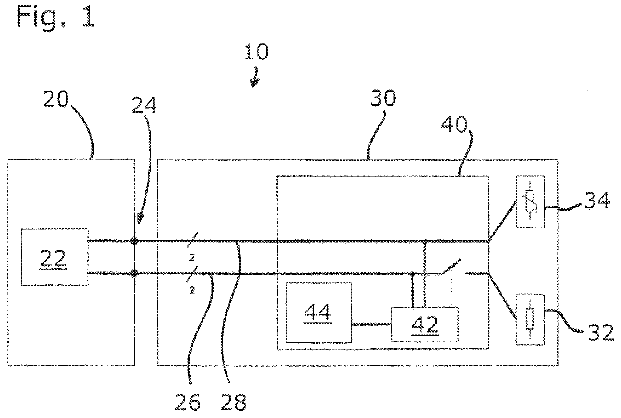
[0034]FIG. 1 schematically shows an endoscope system 10, which comprises an endoscope 30 and a central unit 20, which is configured for the supply and control of the endoscope 30. The central unit 20 comprises a supply unit 22, which is connected via two two-core conductors 26, 28 to a distal heating element 32 and a distal temperature sensor 34, such as a thermistor with a negative temperature coefficient. The heating element 32 can be a heating resistor. The connection is implemented via a coupling interface 24 in which the conductors 26, 28 in the endoscope are connected to external conductors that lead to the supply unit 22. The small numerals 2 below the slashes which cross the two conductors 26, 28 near the connecting lines to the reference signs symbolize the two-core nature of the two conductors 26, 28.

[0035]The elements described thus far form the traditional heating system of an endoscope the distal region of which is shown in FIG. 1 on the right. The heating element 32 an...


PUM


Abstract

A method for operating a heating system of an endoscope. The endoscope including a heating element and a temperature sensor in a distal region of the endoscope and a supply unit outside of the endoscope, the supply unit being connected to the heating element and the temperature sensor, wherein the supply unit activates and deactivates a power supply for the heating element on a basis of a temperature measurement value ascertained by means of the temperature sensor using two-state control, and a monitoring unit including a monitoring circuit which is powered by the power supply for the heating element. The method including: monitoring, with the monitoring circuit, the temperature sensor for a malfunction; and interrupting the power supply to the heating element if the malfunction of the temperature sensor is determined.

Description

CROSS-REFERENCE TO RELATED APPLICATION[0001]The present application is a continuation-in-part application of PCT / EP2020 / 052735 filed on Feb. 4, 2020, which is based upon and claims the benefit to DE 10 2019 103 291.1 filed on Feb. 11, 2019, the entire contents of each of which are incorporated herein by reference.BACKGROUNDField[0002]The present disclosure relates to a method for operating a heating system of an endoscope, which comprises a heating element and a temperature sensor in the distal region of the endoscope and a supply unit outside of the endoscope, the supply unit being connected to the heating element and the temperature sensor, wherein the supply unit activates and deactivates a power supply for the heating element on the basis of a temperature measurement value ascertained by means of the temperature sensor using two-state control, and a heating system and an endoscope system.Prior Art[0003]The present disclosure generally relates to surgical endoscopes and systems, ...

Claims


Application Information

Patent Timeline
Patent Type & Authority Applications(United States)
IPC IPC(8): A61B1/12A61B1/00
CPCA61B1/127A61B2562/0271A61B1/00027A61B1/128G05D23/1917G05D23/24
Inventor JUERGENS, THORSTENPABST, SVENJUNGBAUER, SEBASTIAN
Owner OLYMPUS WINTER & IBE
Why Eureka
Try Eureka