Imaging apparatus, imaging system, movable object, and method for driving imaging apparatus

a technology of imaging apparatus and imaging system, which is applied in the direction of color television details, television system details, television systems, etc., can solve problems such as image degradation, a/d conversion failure to give a correct value, and a failure to compare appropriately

Active Publication Date: 2021-12-02
CANON KK
View PDF0 Cites 2 Cited by
  • Summary
  • Abstract
  • Description
  • Claims
  • Application Information

AI Technical Summary

Benefits of technology

[0007]It is an objective of the present disclosure to provide an imaging apparatus that is capable of high-speed readout of high-quality image signals.
[0011]The present disclosure is able to provide an imaging apparatus that is capable of high-speed readout of high-quality image signals

Problems solved by technology

This may hinder appropriate comparison between the ramp signal and the N-signal, causing the A / D conversion to fail to give a correct value.
That is, image degradation, such as vertical lines and graininess, can result.
In this case, high-speed readout cannot be performed.

Method used


Image

  • Imaging apparatus, imaging system, movable object, and method for driving imaging apparatus
  • Imaging apparatus, imaging system, movable object, and method for driving imaging apparatus
  • Imaging apparatus, imaging system, movable object, and method for driving imaging apparatus

Examples


first embodiment

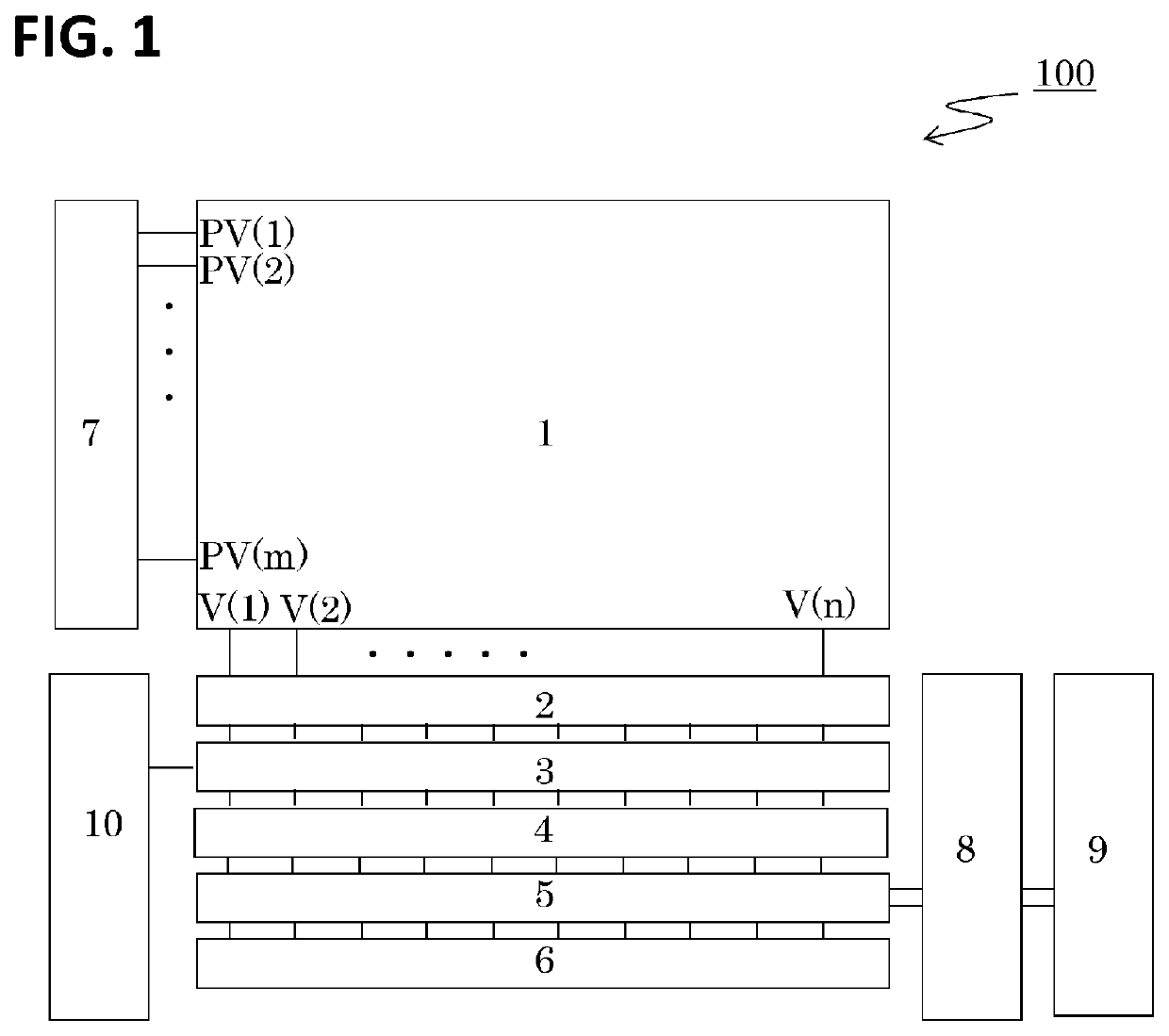
[0022]FIG. 1 shows a block diagram of a configuration of an imaging apparatus 100 according to the present embodiment. The imaging apparatus includes a pixel region 1, column amplifier circuits 2, column comparator circuits 3, column A / D conversion circuits 4, column memory circuits 5, a horizontal drive circuit 6, a vertical drive circuit 7, a data signal calculation circuit 8, an output circuit 9, and a ramp circuit 10.

[0023]The pixel region 1 includes a plurality of photoelectric conversion elements and pixel circuits arranged in a matrix. The pixel circuits arranged in the horizontal direction are controlled by row control signals PV(1), PV(m) (m is a natural number) supplied from the vertical drive circuit 7 for the respective rows. The pixel circuit generates and outputs a pixel signal based on the charge obtained by photoelectric conversion. The signals from the pixel circuits are read out through vertical readout lines V(1), . . . , V (n) (n is a natural number) and the ampl...

second embodiment

[0065]FIG. 5 shows a drive timing chart of a ramp circuit 10 according to a second embodiment. The drive timing chart of FIG. 5 shows the drive timing in one horizontal period as in FIG. 3.

[0066]The second embodiment differs from the first embodiment in the method for driving the ramp circuit 10, but the apparatus configuration is the same as that of the first embodiment. The differences from the first embodiment are described below.

[0067]One feature of this embodiment is that two values, VOF1 for time t12 to immediately before time t13 and VOF2 for time t14 to immediately before time t15, are provided as offset voltages, so that separate reset periods and different offset voltages can be set for different columns. That is, the reset period includes a period in which a first offset voltage for setting a voltage for reference for the column comparator circuits of a first group is output and a period in which a second offset voltage for setting a voltage for reference for the column c...

third embodiment

[0074]FIG. 6 shows a drive timing chart of a ramp circuit 10 according to a third embodiment. The drive timing chart of FIG. 6 shows the drive timing in one horizontal period as in FIG. 3.

[0075]The third embodiment differs from the first and second embodiments in the drive method of the ramp circuit 10. The differences from the first embodiment are described below.

[0076]One feature of this embodiment is that analog signals read from the pixel circuits are read out by the column amplifier circuits 2 with two different gains, high gain Hg and low gain Lg. A low-brightness pixel signal is read with the high gain Hg, and a high-brightness pixel signal is read with the low gain Lg. The data signal calculation circuit 8 or an external circuit of the imaging apparatus performs image synthesis to read out an image with a wider dynamic range.

[0077]To change the ramp gain from a factor of X to a factor of Y (Y>X), the present embodiment also uses the same configuration as the first embodiment...


PUM


Abstract

An imaging apparatus including a ramp voltage generation circuit having a first period for outputting an offset voltage that sets a reference voltage for the comparator circuit, and a second period for outputting a reference voltage having a slope-shaped voltage waveform that varies with time, wherein the generation circuit has a first drive state in which a voltage change amount per unit time of the reference voltage in the second period is a first voltage amount, and a second drive state in which the voltage change amount per unit time of the reference voltage in the second period is a second voltage amount that is less than the first voltage amount, and wherein the offset voltage in the second drive state is less than a value obtained by multiplying the offset voltage in the first drive state by a ratio of the second voltage amount to the first voltage amount.

Description

BACKGROUND OF THE INVENTIONField of the Invention[0001]The present disclosure relates to an imaging apparatus, an imaging system, a movable object, and a method for driving an imaging apparatus.Description of the Related Art[0002]An imaging apparatus is known that removes noise signals by reading out noise signals (hereinafter referred to as N-signals) and pixel signals corresponding to the photoelectric conversion amounts including the noise signals (hereinafter referred to as S signals) and reading out the difference signals as image signals.[0003]Japanese Patent Application Publication No. 2011-24109 describes a drive method in which, of the analog signals read from pixels and amplified, an N-signal and an S signal are compared separately in time with a time-varying ramp signal having a slope-shaped waveform. It also describes a drive method in which the counter starts counting up simultaneously with a temporal change of the ramp signal, and the A / D conversion is performed based ...

Claims


Application Information

Patent Timeline
Patent Type & Authority Applications(United States)
IPC IPC(8): H04N5/374H04N5/378
CPCH04N5/3742H04N5/378H04N25/75H04N25/767
Inventor YAMASHITA, TAKANORIMURAI, HAJIME
Owner CANON KK
Why Eureka
Try Eureka