
Utilizing Multiple Proton Injection Ports in Accelerator Driven Subcritical Reactor for Direct Adopting Spent Fuels from Light Water Reactors

a technology of subcritical reactors and proton injection ports, which is applied in the direction of nuclear reactors, reactor fuel susbtances, greenhouse gas reduction, etc., can solve the problems of not having a sound, practical and effective method to handle spent fuels, and neither the permanent solution to address nuclear waste, and the two strategies currently suffer significant drawbacks politically, technically, and economically. , to achieve the effect of enhancing the effectiveness of fission rate and easing the storage problem of spent fuel

Pending Publication Date: 2021-12-16
CHAO JIATSONG JASON
View PDF0 Cites 0 Cited by
  • Summary
  • Abstract
  • Description
  • Claims
  • Application Information

AI Technical Summary

Benefits of technology

This patent discusses a method of using spent fuels from light water reactors in an Accelerator Driven Subcritical reactor (ADS) to produce power without generating additional radioactive materials. This approach also reduces the storage problem for the spent fuels and eases concerns over the proliferation of nuclear weapons. The use of multiple proton ports in the ADS reactor allows for the creation of multiple neutron sources at various axial locations, which enhances the effectiveness of fission rates for transmutation and energy production. Additionally, the external modulation of proton fluxes enables the creation of different neutron sources to accommodate the positional variation in the spent fuels of different ratios of minor actinides and major actinides.

Problems solved by technology

So far there has not been a permanent solution to address the nuclear waste issue worldwide, nor has been a sound, practical, and effective method to handle the spent fuels generated from light water reactors after their use for producing nuclear power commercially.
Both strategies currently suffer significant drawbacks politically, technically, and economically.
Currently there is not any near-term solution in sight for implementation nor any long-term plan to handle the spent fuels, by either strategy.
As of today, the option of building a repository to store all the spent fuels has not been successful.
But no site has a date predicted for its opening for operation.
Too many political and economic issues remain unresolved that have caused the congestion of the temporary storage space for spent fuels generated in nuclear power plants everywhere in the world.
The work is now stopped because of strong opposition politically and no one could predict when the work would be resumed.
It seems uneconomical to allow the financial investment on the development of a repository site without receiving any return.
From energy efficiency perspective, it is not economical to leave the plutonium and uranium in spent fuels without their future utilization, although recent studies indicated that it would be better not to reprocess spent fuels due to the high costs of extracting plutonium and uranium off spent fuels and making new fuels.
Shortfalls of Reprocessing Spent Fuels
The recycling strategy is facing major obstacles too.
Yet, problems associated with fuel recycling surfaced in recent years that would make this strategy less attractive.
Yet, while the reprocessing technology could effectively extract plutonium off the spent fuels, the remaining residual high-level wastes after reprocessing would have to return to the country that owns the spent fuels.
To many countries this approach does not eliminate nuclear wastes as a final resolution but a strategy to delay the time of confronting the real issue.
While the technologies for extracting plutonium was effective and the plutonium has been used as a new fuel, the involved intermediate processes have created additional and costly problems unexpectedly.
Yet, the involved processes have created excessive additional radioactive materials.
Although most of these new materials are not considered high level wastes but intermediate or low-level wastes, they still require significant and unexpected costs for their handling and cleanup.
For this reason, continuing the efforts in recycling spent fuels has not been encouraged.
It is a costly endeavor to extract plutonium from the spent fuels as it involves tedious and complex chemical and physical processes to perform the separation of plutonium and uranium from the spent fuels or the wastes.
Safety and shielding measures are heavy capital investments for these endeavors that could contribute to the staggering cost.
In addition to the cost incurred by the extracting tasks, there is an additional cost for making the new fuels for reuse in the power producing reactors or for fueling an Accelerator Driven Subcritical reactor treating minor actinides as the ultimate wastes for their transmutation.
Yet, the fast breeder reactor concept since its inception 40 years ago has not been implemented successfully by the nuclear industries worldwide thus far.
Subcritical systems do not have the ability to make the chain reactions as the critical reactors do and therefore cannot generate enough neutrons by fission to sustain the nuclear reactions for continuously eliminating minor actinides.
There are major drawbacks in the approach of using the current versions of ADS.
The involved intermediate processes would create additional radioactive wastes with added cost.
Such undesirable conditions share the same difficulties with the reprocessing tasks of making the advanced fuels for power production such as the MOX fuels for light water reactors or for fast reactors.
There are difficulties arising from the additional nuclear wastes generated during fuel recycling.
Although these additional nuclear wastes are not of high-level radioactivity, they are still costly to handle and clean up.
The cleanup cost is a huge and increasing number that the recycling hosts must face and have faced unexpectedly during the past years.
(23) These factors apparently are viewed as an obstacle for continuing extracting plutonium off the spent fuels.

Method used


Image

  • Utilizing Multiple Proton Injection Ports in Accelerator Driven Subcritical Reactor for Direct Adopting Spent Fuels from Light Water Reactors
  • Utilizing Multiple Proton Injection Ports in Accelerator Driven Subcritical Reactor for Direct Adopting Spent Fuels from Light Water Reactors
  • Utilizing Multiple Proton Injection Ports in Accelerator Driven Subcritical Reactor for Direct Adopting Spent Fuels from Light Water Reactors

Examples


embodiment 1

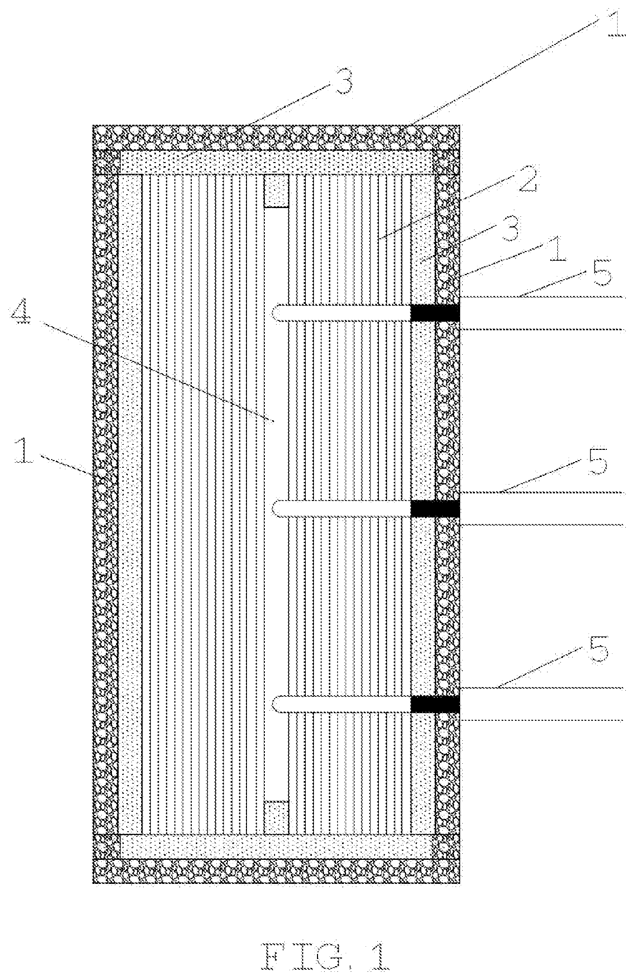
[0125]Three sideway proton intake ports 5 are connected to an accelerator driven subcritical reactor and deliver protons into the core to collide with the target 4 placed in the center of the ADS reactor core. The vertical cross section side view for this arrangement is presented in FIG. 1. In this figure, it shows the ADS core includes spent fuels 2 taken from light water reactors, and an external layer of reflector materials 3. Another layer outward along the radial direction is the shielding material 1.

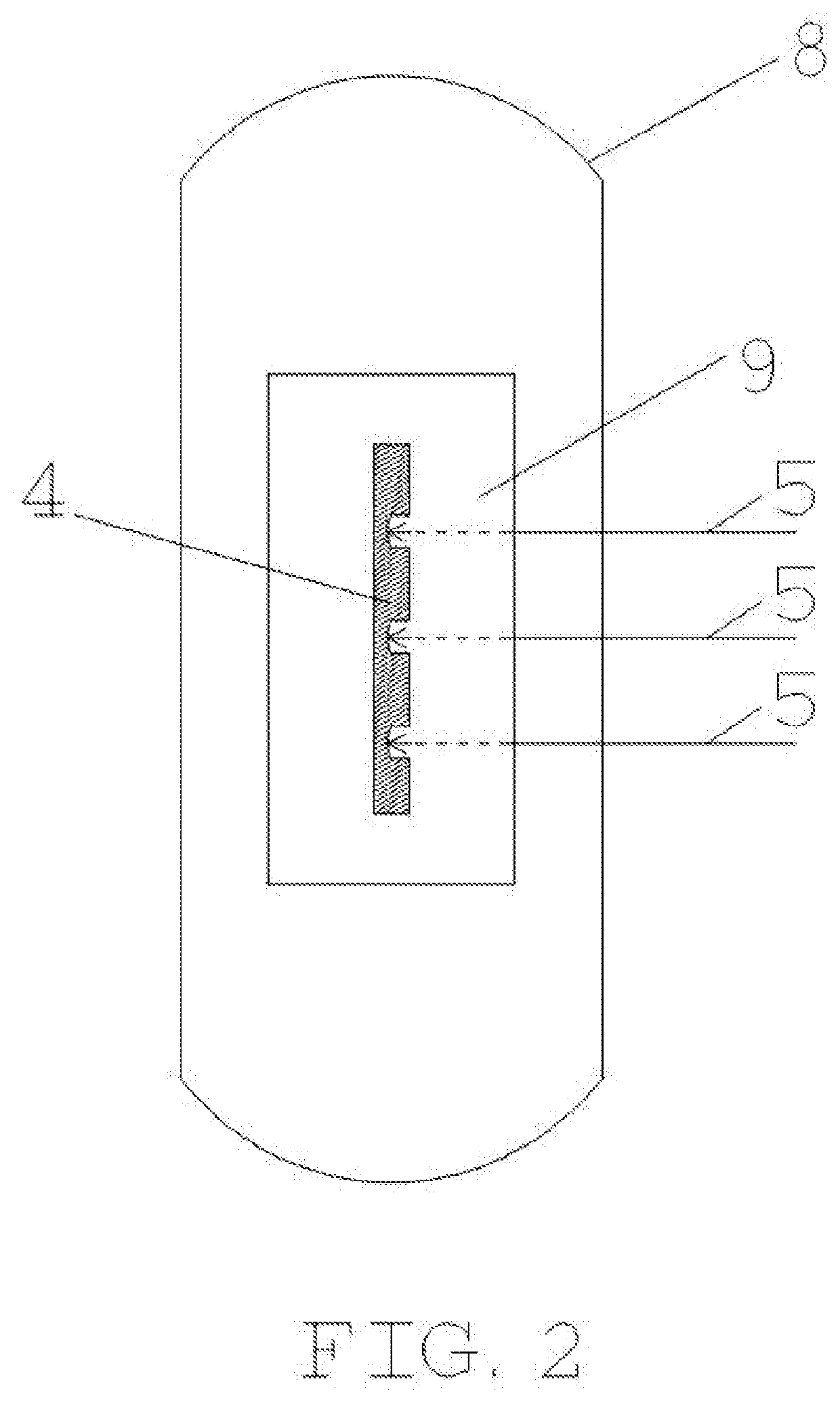
[0126]FIG. 2 shows the reactor vessel 8 of the accelerator driven subcritical core 9 with three sideway proton intake ports, each port 5 delivers protons from one or more accelerators. The protons are delivered to the ADS core 9 to collide with the spallation targets 4 for producing neutrons.

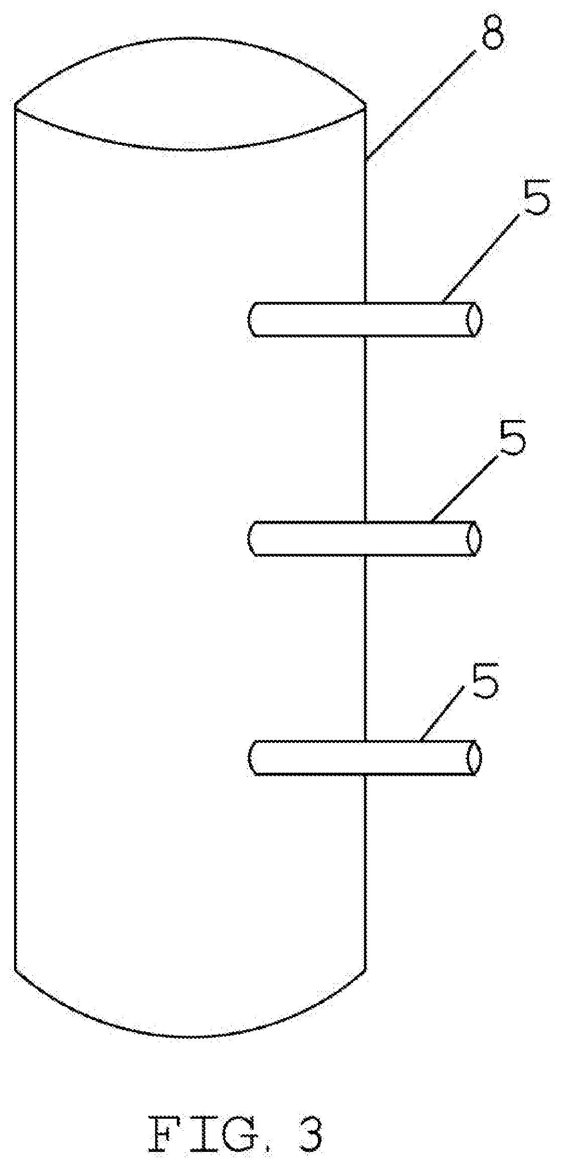
[0127]FIG. 3 shows that the three sideway proton intake ports 5 are connected to and penetrate through the reactor vessel wall 8.

embodiment 2

[0128]Embodiment 2 is a design of a target of two spallation locations for receiving two protons streams, one from the top of the reactor and the other from the bottom of the reactor.

[0129]FIG. 4 shows the vertical cross-sectional view for half of the ADS core. Two proton intake ports 10 are connected to the ADS core, one port 10 delivers protons from top of the reactor, and the other from bottom of the core. The spallation target 15, the fuels 2, reflector 3, and the shielding 1 are shown in the figure.

[0130]FIG. 5 shows the vertical cross-sectional view for the ADS core with fuel elements and two proton intake ports 10. One proton port enters the reactor from the top of the core and the other enters from the bottom of the core.

[0131]FIG. 6 shows a 3D view of the ADS core, with fuel elements 2 and two two-way proton intake ports 10.

[0132]FIG. 7 shows a reactor vessel that houses the ADS core with two proton intake ports connected to the core, one from top, and the other from bottom...

embodiment 3

[0133]FIG. 8 shows one proton intake port, entering the core from top of the vessel for delivering protons to the core. The target is specifically designed to have a Step Down shape to accommodate two proton streams for colliding with the target at two different axial locations along the center axis of the core such that there will be two neutron sources located strategically for maximizing the effectiveness of nuclear reactions.

[0134]A modulation unit in the intake port on top of the vessel could deliver protons for the two proton streams at different energies and fluxes. This arrangement could make the neutrons generated at the two target locations with different energies and quantities. The modulation unit 20 on top of the vessel that would have magnet arrangements inside to perform the functions of bending the proton flow direction from horizontal to downward as well as splitting the proton flows to two proton steams of different energies and fluxes.


PUM


Abstract

The new features of an accelerator driven subcritical reactor disclosed by this invention include the multiple intake ports connected to the reactor vessel for delivering protons from one or more accelerators to accommodate the full length LWR spent fuels for furnishing the desirable neutron distribution in a subcritical core to incinerate nuclear wastes. This is based on the notion of adopting the spent fuels in intact form to feed directly to the newly designed subcritical core. External modulators in the proton intake ports have the ability of splitting the fluxes and adjusting their energy from one or more accelerators to form multiple proton streams arriving at different axial locations in the spallation target for creating multiple neutron sources. The new design could combine the cycles of reprocessing spent fuels, manufacturing fuels for reuse, and incinerating minor actinides into one single cycle.

Description

BACKGROUND OF THE INVENTIONTechnical Field[0001]The present invention relates to transmutation of nuclear waste in accelerator driven subcritical (ADS) reactors.Background Art[0002]Three categories of prior art for this invention are identified: 1) the U.S. patents, 2) patent applications, and 3) existing ADS projects reported in the literature. As this invention falls in the category of using an accelerator driven subcritical reactor to eliminate high level nuclear waste of minor actinides, many other look-alike subjects or prior art would not fit in well with this category. These unfitted categories include the fast breeder reactors, molten salt reactors, high temperature gas cooled reactors, fusion reactors, hybrid reactors, reactors for energy multiplication purposes, or light water reactors with transmutation features, none of which are listed as a prior art.U.S. patent Documents3,349,001October 1967Stanton4,309,249January 1982Steinberg et al.5,160,696November 1992Bowman5,768,3...

Claims


Application Information

Patent Timeline
IPC IPC(8): G21G1/02G21C1/30G21C3/42
CPCG21G1/02G21C3/42G21C1/303G21G1/08G21C1/30G21F9/30Y02E30/30
Inventor CHAO, JIATSONG JASON
Owner CHAO JIATSONG JASON
Learn More