Nanofiber-hydrogel composites for cell and tissue delivery

a technology of nanofiber and hydrogel, applied in the field of composite materials, can solve the problems of difficult conventional treatment of congenital malformations, soft tissue defects resulting from trauma, oncologic resection, fibrosis and encapsulation, etc., and achieve the effect of improving the quality of soft tissue reconstruction and improving the properties

Pending Publication Date: 2021-12-30
THE JOHN HOPKINS UNIV SCHOOL OF MEDICINE
View PDF1 Cites 0 Cited by
  • Summary
  • Abstract
  • Description
  • Claims
  • Application Information

AI Technical Summary

Benefits of technology

[0040]These and other embodiments are disclosed or are obvious from and encompassed by, the following Detailed Description.

Problems solved by technology

Soft tissue defects resulting from trauma, oncologic resection, or congenital malformation are difficult to treat by conventional means.
Current therapies, including tissue rearrangements or tissue transfer, cause donor site defects.
Other therapies, such as prosthetic implants, lead to fibrosis and encapsulation.
Existing strategies to promote tissue ingrowth are also inadequate for the treatment of soft tissue defects.
Current acellular matrices result in flat, fibrotic sheets of tissue rather than the soft, three-dimensional tissue required for ideal reconstructions.
Finally, while fat grafting can restore soft tissue defects, its wider use is hampered by variable graft survival and limited volumes of restoration.
For example, cells experience mechanical and structural challenges that can result in cell death and compromise cell function at each stage of cell transplantation process (pre-injection, injection, acute post-injection, and long-term survival).
While several hydrogels have shown some benefits in soft tissue reconstruction and stem cell transplantation, there is no current material that is able to address all of the mechanical challenges in succession.
Under these conditions, however, host tissue cells (e.g., adipocyte progenitors and endothelial progenitors) are not able to penetrate and grow into the scaffolds.
In case of degradable hydrogels, scarring and fibrous tissue formation are typical because ingrowth of host tissue occurs too slowly, or at least at a pace slower than the absorption of the fiber material.
These nanofibers, however, do not offer macroscopic structures, making them difficult to use as 3D scaffolds.
Many commercialized hydrogel fillers cause moderate to severe inflammation in the patient, while not retaining full original volume over time.

Method used


Image

  • Nanofiber-hydrogel composites for cell and tissue delivery
  • Nanofiber-hydrogel composites for cell and tissue delivery
  • Nanofiber-hydrogel composites for cell and tissue delivery

Examples


example 1

orming Composite with Reduced Inflammation Profiles

[0269]An in situ-forming composite was developed comprising 5 mg / mL of thiolated HA (HA-SH), 10 mg / mL of polycaprolactone (PCL) fibers and the concentration of PEGDA set to match the thiol concentration 1:1 with the combined acrylate and maleimide concentrations (5 mg / mL). The components were mixed together to react approximately 30 minutes before surgery in order to begin gelation, with the bulk of the gelation being completed in situ.

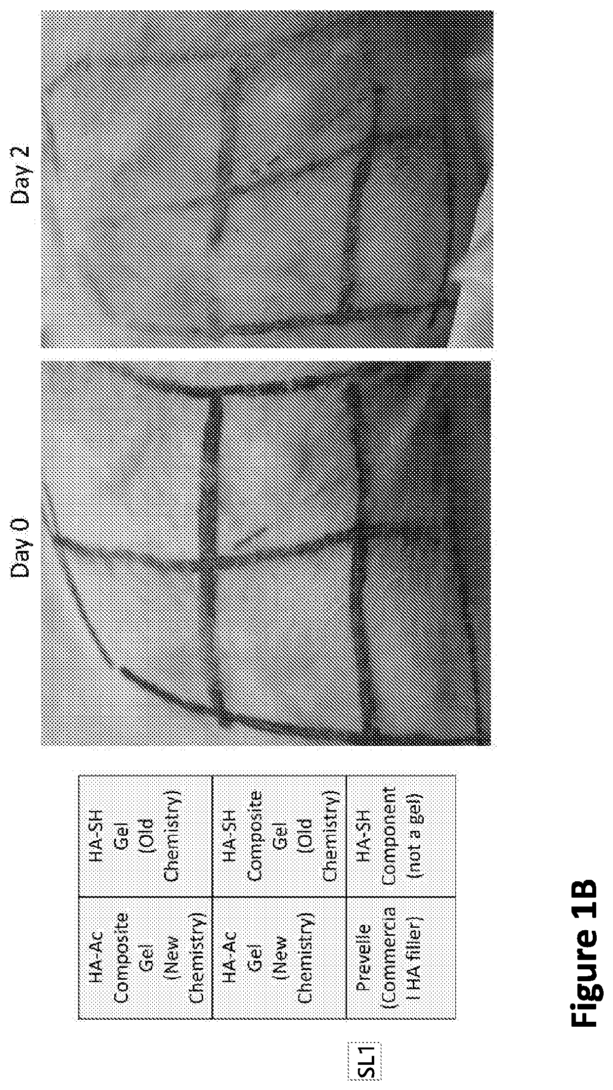
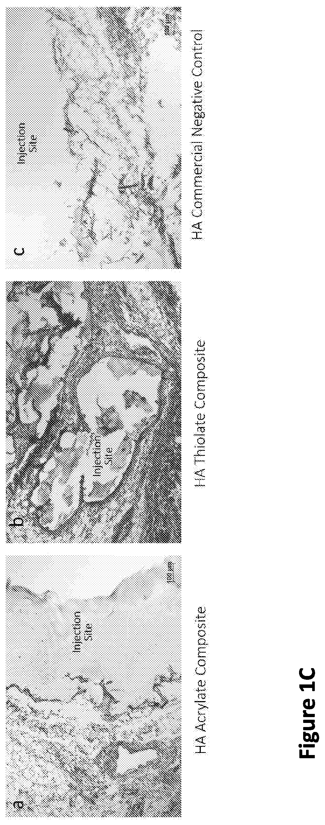
[0270]While gelation success was achieved in vitro and in animals (rodents and rabbits by subcutaneous (s.c.) injection), the chemistry preparation utilizing the thiolated-HA caused short-term moderate inflammation when injected in the subcutaneous rabbit model. In order to produce a composite formulation with reduced inflammation, the reactive groups between the HA and PEG were reversed, keeping an earlier formulation comprising a fiber-maleimide component.

[0271]As shown in FIG. 1A, the upward arrows...

example 2

ed Composite Beads with New Composition

[0277]To improve storage stability and make the gel simpler and more consistent for the end-user, a gel was formed comprising a pre-reacted, beaded formulation, wherein the formulation (7 mg / mL HA-Ac, 8 to 10 mg / mL of fibers with maleimide, and 6.9 m / mL of PEGSH) is fully reacted in bulk at 37° C. By pre-reacting the gel during manufacturing, the labile functional groups did not need to be protected, and the need for extensive mixing and curing by the end-user was removed.

[0278]The bulk gel is formed into 150 or 250 μm beads, then lyophilized in an isotonic solution of sucrose, trehalose, and sodium chloride (to protect the microstructure during the drying process and extend the product's shelf life). The gel beads are then reconstituted with water and within seconds are ready for injection, with the same storage modulus as prior to lyophilization. Optical microscopy images of the beaded composite are shown in FIG. 2. FIG. 2A shows the composit...

example 3

tion of Rheological Properties of Composite Beads of Different Sizes

[0280]The beads of different sizes were prepared using screens with mesh sizes of 1 mm, 250 μm, 150 μm, and 90 μm. The particles were assessed for injectability (assessment from plastic surgeons) and rheological properties. The 1000-μm beads were not injectable as their diameter was much larger than the bore size of a 25-gauge needle, while the 90-μm beads were heavily damaged in the beading process; therefore, both sizes were excluded from further study. Both the 250-μm and 150-μm bead groups injected smoothly through a 27-gauge needle. These bead sizes are of similar magnitude as the inner diameter of relevant needle sizes (25-gauge=250 μm, 27-gauge=210 μm, and 30-gauge needle=160 μm). The rheological properties of the 250 μm and 150-μm beads are shown in FIG. 3. The storage modulus decreases slightly when the solid plug of material is formed into beads, but the resulting beads are within our target stiffness rang...


PUM

PropertyMeasurementUnit
concentrationaaaaaaaaaa
mean lengthaaaaaaaaaa
mean sizeaaaaaaaaaa

Abstract

A composite material can include a gel and at least one nanostructure disposed within the gel. A method for healing a soft tissue defect can include applying a composite material to a soft tissue defect, wherein the composite material includes a gel and a nanostructure disposed within the gel. A method for manufacturing a composite material for use in healing soft tissue defects can include providing a gel and disposing nanofibers within the gel.

Description

[0001]This application claims the benefit of U.S. Provisional Application 62 / 669,287 filed May 9, 2018, which is incorporated by reference herein in its entirety.[0002]This invention was made with government support under grant no. 1R21NS085714 awarded by the U.S. National Institutes of Health and grant no. DMR1410240 awarded by the National Science Foundation. The government has certain rights in the invention.BACKGROUND1. Field[0003]The present disclosure relates to composite materials and methods that restore lost soft tissue volume while promoting soft tissue regeneration. The present invention also relates to composite materials and methods for cell and tissue delivery for cosmetic, reconstructive, and cellular therapies.2. Description of Related Art[0004]Soft tissue defects resulting from trauma, oncologic resection, or congenital malformation are difficult to treat by conventional means. Current therapies, including tissue rearrangements or tissue transfer, cause donor site d...

Claims


Application Information

Patent Timeline
Patent Type & Authority Applications(United States)
IPC IPC(8): A61L27/38A61L27/18A61L27/20A61L27/48A61L27/52A61L27/54A61L27/56A61L27/58
CPCA61L27/3834A61L27/18A61L27/20A61L27/3808A61L27/3895B82Y5/00A61L27/52A61L27/54A61L27/56A61L27/58A61L27/48A61L27/3804A61L2300/414A61L2300/622A61L2400/06A61L2400/12A61L2430/34C08L5/08C08L67/04A61L27/38A61L2300/412A61L2300/602A61L27/44A61M5/19A61M2202/08A61M2202/09A61L2300/604B82Y30/00B82Y40/00
Inventor REDDY, SASHANKMARTIN, RUSSELLLI, XIAOWEICHANG, CALVINCOLBERT, KEVINMAO, HAI-QUAN
Owner THE JOHN HOPKINS UNIV SCHOOL OF MEDICINE
Why Eureka
Try Eureka