Splicing laser interference lithography equipment suitable for large-area nanostructure fabrication

A spliced, large-area technology, used in microlithography exposure equipment, photolithographic process exposure devices, etc., can solve the problems of unstable exposure system, mobile platform is easily affected by gravity, etc., and achieve convenient movement and stable exposure system. Effect

Active Publication Date: 2017-01-04
SUNPHIRE OPT TRONIC
View PDF9 Cites 0 Cited by
  • Summary
  • Abstract
  • Description
  • Claims
  • Application Information

AI Technical Summary

Problems solved by technology

The two important lithography technologies of NPSS are nanoimprint (nanoimprint) and laser interference lithography (laser interference lithography, LIL). In the design of traditional laser interference lithography equipment, the Lloyd-mirror system is mainly used. , the substrate is fixed upright, therefore, the mobile platform carrying the substrate is easily affected by gravity, causing the exposure system to be unstable

Method used


Image

  • Splicing laser interference lithography equipment suitable for large-area nanostructure fabrication
  • Splicing laser interference lithography equipment suitable for large-area nanostructure fabrication

Examples


Embodiment Construction

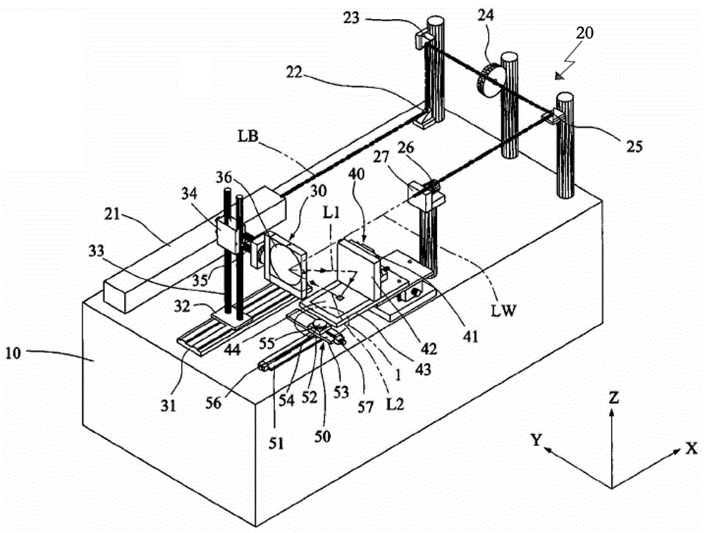
[0027] Such as figure 1 As shown, the present invention discloses a spliced ​​laser interference lithography device suitable for the manufacture of large-area nanostructures. It consists of a main body 10 and a laser light wave supply unit 20 installed on the main body 10, a reflection mechanism 30, and an L-shaped fixing mechanism. 40 and substrate carrier 50.

[0028] The laser light wave supply unit 20 includes a laser light source generator 21, a shutter 24, a pinhole 26 and a lens 27, and the laser beam LB emitted by the laser light source generator 21 is emitted through the shutter 24, the pinhole 26 and the lens 27 to form laser light Wave LW. In order to make the structure of the whole device more compact, the laser light wave supply unit 20 also includes a first mirror 22, a second mirror 23 and a third mirror 25, and the first mirror 22 and the second mirror 23 are installed on the laser source generator 21 and the shutter 24. Between, the laser beam LB that laser ...


PUM


Abstract

The invention discloses a splicing laser interference lithography equipment suitable for the manufacture of large-area nanometer structures, which is composed of a main body, a laser light wave supply unit installed on the main body, a reflection mechanism, an L-shaped fixing mechanism and a substrate carrier; The radiation wave supply unit includes a laser light source generator, a shutter, a pinhole and a lens; the reflection mechanism includes a three-dimensional movable bracket and a second reflector, the second reflector is installed on the three-dimensional movable bracket, and the second reflector corresponds to the lens and accepts the laser beam. emit light waves; the L-shaped fixing mechanism consists of a vertical fixing seat, a first reflector, a horizontal fixing seat and a photomask. The table includes an X-direction shaft seat, an X-direction moving shaft, an X-direction driving mechanism, a Y-direction shaft seat, a Y-direction moving shaft, a Y-direction driving mechanism and a substrate clamp, and the position of the substrate clamp is lower than the horizontal fixed seat. The invention makes the exposure system more stable.

Description

technical field [0001] The invention relates to a splicing laser interference lithography equipment suitable for making large-area nanostructures, and is suitable for the processing and manufacturing fields of semiconductors, LEDs, MEMS and 3C. Background technique [0002] With the development of various semiconductor, micro-electromechanical, display and solid-state lighting technologies, the requirements for lithography technology tend to develop towards large-scale and graphic miniaturization; taking high-brightness blue and white light-emitting diodes (LEDs) as examples, patterned sapphire The adoption of (PSS) substrates has occupied the mainstream position, and the related technology, especially the lithography part, has played a technical bottleneck and is also the key to development. [0003] The traditional process of using a photomask with an exposure stepper (stepper) encounters challenges when the size of the substrate is increasing, especially the flatness and ...

Claims


Application Information

Patent Timeline
Patent Type & Authority Patents(China)
IPC IPC(8): G03F7/20
Inventor 刘崇志
Owner SUNPHIRE OPT TRONIC
Why Eureka
Try Eureka