Stretch wrapping machine with packaging material tail treatment

a wrapping machine and wrapping material technology, applied in the direction of wrapping material feeding apparatus, transit packaging, packaging, etc., can solve the problems of affecting the operation of the electrical and mechanical actuator, and wasting packaging material and loosely wrapped loads,

Active Publication Date: 2022-01-06
LANTECH COM
View PDF3 Cites 1 Cited by
  • Summary
  • Abstract
  • Description
  • Claims
  • Application Information

AI Technical Summary

Benefits of technology

[0021]Also, in some embodiments, directing the first flow of fluid towards the packaging material tail reduces bunching of the packaging material tail widthwise and / or lengthwise prior to coming into contact with the side of the load. In addition, in some embodiments, directing the second flow of fluid towards the packaging material tail increases adherence of the packaging material tail to the side of the load. Moreover, in some embodiments, directing the second flow of fluid towards the packaging material tail is performed after the packaging material tail comes into contact with the side of the load. In some embodiments, directing the second flow of fluid towards the packaging material tail is performed before the packaging material tail comes into contact with the side of the load. Further, in some embodiments, directing the second flow of fluid towards the packaging material tail is performed concurrently with the packaging material tail coming into contact with the side of the load. In some embodiments, directing the second flow of fluid towards the packaging material tail includes directing a plurality of pulsed flows of fluid towards the packaging material tail. Moreover, in some embodiments, the plurality of pulsed flows of fluid impact the packaging material tail at a plurality of locations across a width of the packaging material tail.
[0031]Consistent with another aspect of the invention, a method of wrapping a load with packaging material may include moving a packaging material holder to a first position adjacent a side of the load while the packaging material holder engages a leading end of a web of packaging material, wrapping the load while the packaging material holder is in the first position by generating relative rotation between a packaging material dispenser and the load about a center of rotation, where wrapping the load at least partially wraps packaging material over the packaging material holder, disengaging the packaging material holder from the web of packaging material and moving the packaging material holder to a second position and away from the side of the load, positioning the web of packaging material adjacent to the packaging material holder and to a cutting assembly disposed upstream of the packaging material holder, engaging the web of packaging material with the packaging material holder, severing the web of packaging material between a corner of the load and the packaging material holder to form a packaging material tail extending from the corner of the load, directing a first flow of fluid towards the packaging material tail from a first position generally upstream of a free end of the packaging material tail and at a first angle relative to the side of the load while the free end of the packaging material tail is unsupported to cause the packaging material tail to come into contact with the side of the load, and after the packaging material tail comes into contact with the side of the load, directing a second flow of fluid towards the packaging material tail from a second position and at a second angle relative to the side of the load to increase adherence of the packaging material tail to the side of the load, where the first angle is an acute angle relative to the side of the load and an acute angle relative to a plane extending between the corner of the load and the cutting assembly, the second angle is substantially orthogonal relative to the side of the load, and the first flow of fluid has a higher volume, a longer duration, and a lower velocity than the second flow of fluid.

Problems solved by technology

The attachment or tying of the packaging material makes packaging material removal more difficult after the load has been shipped to its destination.
Such packaging material clamps may create a “tenting” effect during wrapping due to the distance between the clamp and the load during wrapping, resulting in wasted packaging material and loosely wrapped loads.
In addition, such clamps are generally expensive and may require costly maintenance for the electrical and mechanical actuators.
Conventional wipe down mechanisms, however, are often relatively complex and may be difficult to incorporate into some applications, including, for example, applications where a load is supported on the ground rather than on a conveyor or turntable.
Furthermore, some wipe down mechanisms can produce inconsistent results, with tails that are inadequately adhered to the side of the load.
Such unadhered tails, however, can be problematic during later transportation and storage as they can present a snagging hazard for fork trucks and other load racking devices.

Method used


Image

  • Stretch wrapping machine with packaging material tail treatment
  • Stretch wrapping machine with packaging material tail treatment
  • Stretch wrapping machine with packaging material tail treatment

Examples


Embodiment Construction

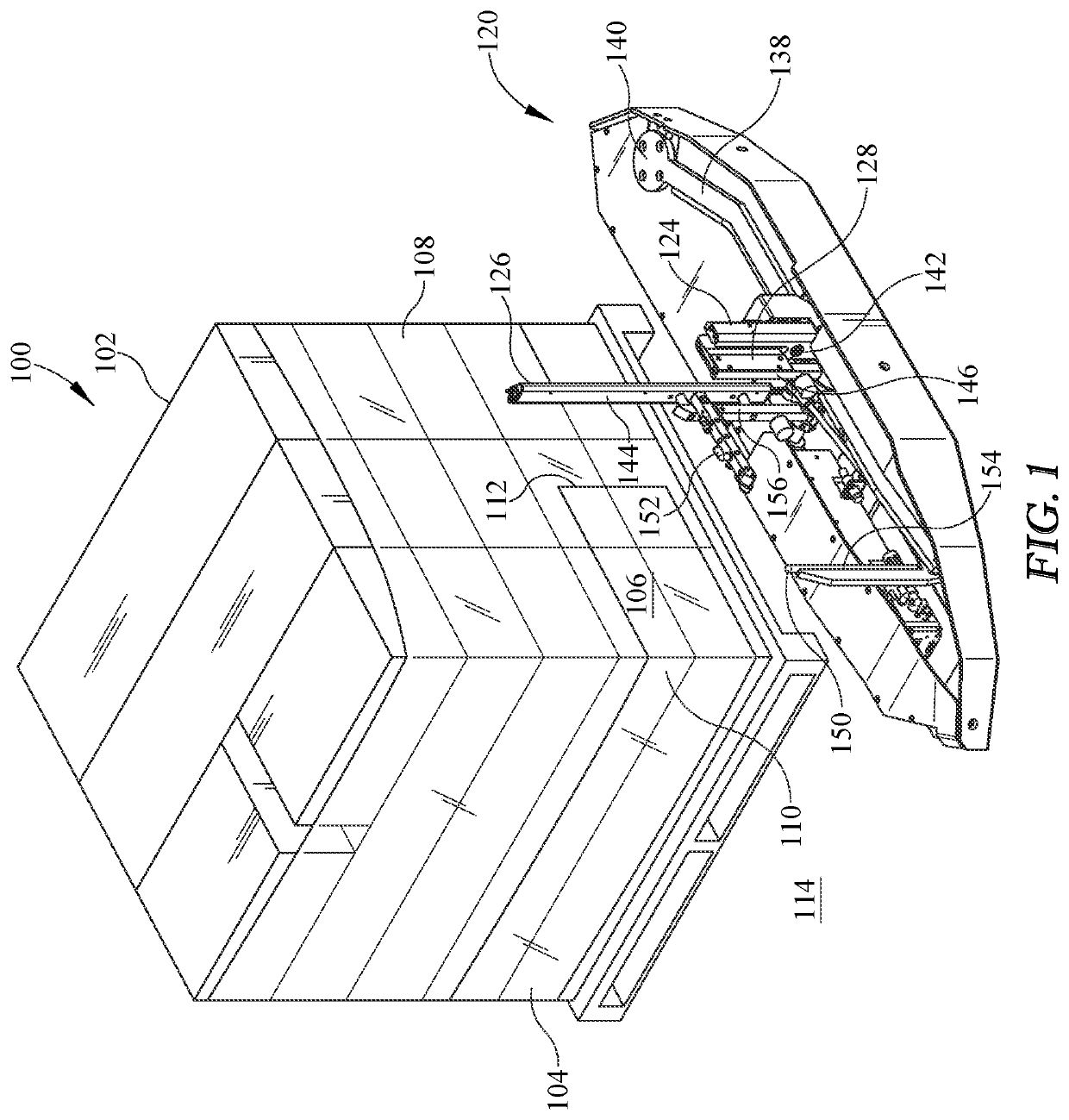
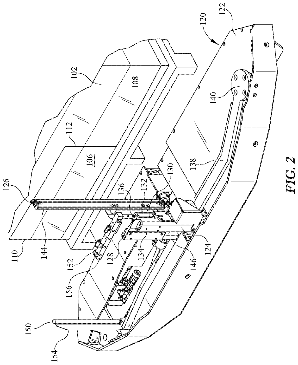
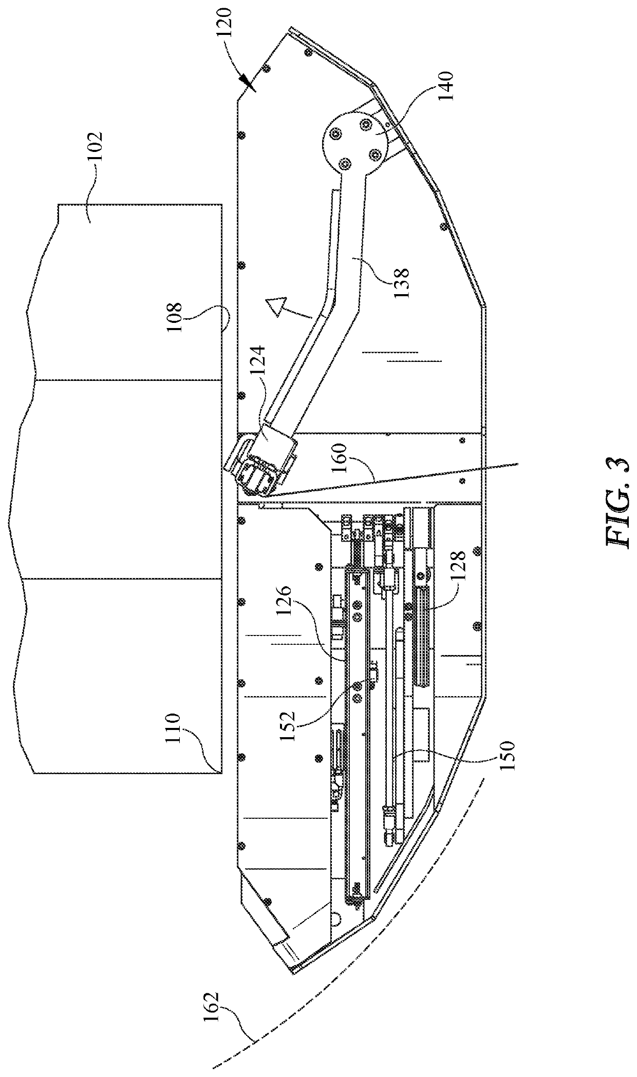
[0043]Embodiments consistent with the invention may utilize pressurized fluid flow directed upstream and / or in two or more directions to assist in adhering a packaging material tail to the side of a load at the completion of a wrapping operation. In this regard, a packaging material tail generally refers to a portion of a web of packaging material that extends between a load and a packaging material dispenser at the completion of a wrapping operation, and generally the portion of the web that extends between a last corner of the load around which the web of packaging material is wrapped and a cutting assembly that severs the web of packaging material at the completion of the wrapping operation.

[0044]A packaging material tail may, in many instances, be shorter in length than the width of the side of the load to which it adheres, and it is generally desirable to adhere the packaging material tail to the side of the load to minimize the risk that the packaging material tail will detach...


PUM

PropertyMeasurementUnit
angleaaaaaaaaaa
angleaaaaaaaaaa
heightaaaaaaaaaa

Abstract

A method, apparatus and program product utilize pressurized fluid flow from a position generally upstream of a free end of a packaging material tail and at an acute angle relative to the side of a load while the free end of the packaging material tail is unsupported and / or utilize pressurized fluid flow in two or more directions and from two or more positions to assist in adhering a packaging material tail to the side of a load at the completion of a wrapping operation.

Description

BACKGROUND OF THE INVENTION[0001]Various packaging techniques have been used to build a load of unit products and subsequently wrap them for transportation, storage, containment and stabilization, protection and waterproofing. One system uses wrapping machines to stretch, dispense, and wrap packaging material around a load. The packaging material may be pre-stretched before it is applied to the load. Wrapping can be performed as an inline, automated packaging technique that dispenses and wraps packaging material in a stretch condition around a load on a pallet to cover and contain the load. Stretch wrapping, whether accomplished by a turntable, rotating arm, vertical rotating ring, or horizontal rotating ring, typically covers the four vertical sides of the load with a stretchable packaging material such as polyethylene packaging material. In each of these arrangements, relative rotation is provided between the load and the packaging material dispenser to wrap packaging material abo...

Claims


Application Information

Patent Timeline
Patent Type & Authority Applications(United States)
IPC IPC(8): B65B11/04B65B41/12B65B61/06B65B51/16
CPCB65B11/04B65B51/16B65B61/06B65B41/12B65B11/025
Inventor LANCASTER, III, PATRICK R.LIMOUSIN, JEAN-LOUIS
Owner LANTECH COM
Why Eureka
Try Eureka