Dual pole switch detection circuit

a detection circuit and dual-pole technology, applied in the direction of electric variable regulation, process and machine control, instruments, etc., can solve the problems of the switch used to disconnect the power, the three-phase power supply of the aircraft oven can be disabled, and the switch itself can fail

Active Publication Date: 2022-01-13
BE AEROSPACE INCORPORATED
View PDF0 Cites 1 Cited by
  • Summary
  • Abstract
  • Description
  • Claims
  • Application Information

AI Technical Summary

Problems solved by technology

Three-phase power supplied to an aircraft oven can be disabled when a safety system detects a problem.
The switches used to disconnect this power can themselves fail in various failure modes, so it is necessary to monitor the switches.

Method used


Image

  • Dual pole switch detection circuit

Examples


Embodiment Construction

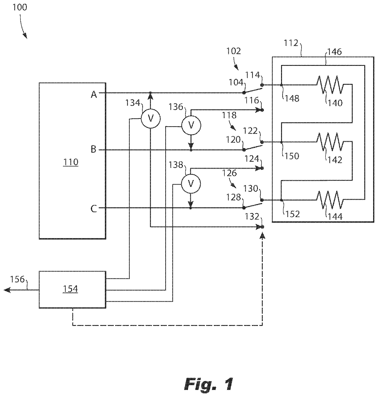
[0015]Reference will now be made to the drawings wherein like reference numerals identify similar structural features or aspects of the subject disclosure. For purposes of explanation and illustration, and not limitation, a partial view of an embodiment of a system in accordance with the disclosure is shown in FIG. 1 and is designated generally by reference character 100. The systems and methods described herein can be used to monitor switches such as used for safety switches for galley ovens in aircraft.

[0016]The system 100 includes a first switch 102 having a single pole 104 and dual throws 114, 116. The single pole 104 is on a supply side of the first switch 102, i.e. connected to the power supply or source 110. The dual throws 114, 116 are on a load side of the first switch 102, e.g. with the load 112. One of the dual throws 114, 116 include a normally open (NO) throw 114 and a normally closed (NC) throw 116. A second switch 118 has a single pole 120 and dual throws 122, 124. Th...


PUM


Abstract

A system includes three switches each having a single pole and dual throws. The respective single pole is on a supply side of the each respective switch. The dual throws are on a load side of each respective switch, and include a respective normally open (NO) throw and a respective normally closed (NC) throw. A first voltage detector is connected from the single pole of the first switch to the NC throw of the third switch. A second voltage detector is connected from the single pole of the second switch to the NC throw of the first switch. A third voltage detector is connected from the single pole of the third switch to a NC throw of the second switch.

Description

CROSS REFERENCE TO RELATED APPLICATION[0001]This application claims the benefit of priority to U.S. Provisional Patent Application Ser. No. 63 / 050,919, filed on Jul. 13, 2020, the disclosure of which is incorporated herein by reference in its entirety.BACKGROUND1. Field[0002]The present disclosure relates to power handling, and more particularly to detecting three phase power, e.g., for ovens or other equipment in aircraft.2. Description of Related Art[0003]Three-phase power supplied to an aircraft oven can be disabled when a safety system detects a problem. The switches used to disconnect this power can themselves fail in various failure modes, so it is necessary to monitor the switches. In case one switch fails, the other switches can be disabled, assuring system safety. A typical state monitoring system for the switches is performed by comparing the voltage on a power line before and after switching the switch to compare with the intended state.[0004]The conventional techniques h...

Claims


Application Information

Patent Timeline
Patent Type & Authority Applications(United States)
IPC IPC(8): B64D41/00G05F1/625B64D11/04
CPCB64D41/00B64D11/04G05F1/625G01R31/008G01R31/3277
Inventor MULDERS, DENNISHUIJSING, HANS
Owner BE AEROSPACE INCORPORATED
Why Eureka
Try Eureka