Three dimensionally periodic structural assemblies on nanometer and longer scales

a three-dimensional periodic and nanometer-long technology, applied in the direction of nanostructure manufacturing, crystal growth process, chemical/physical process, etc., can solve the problems of limited success in creating three-dimensional periodic structures, degrade the desired properties resulting from infiltrated materials, and achieve low melting point, easy de-infiltration, and minimize unfavorable interfacial energy

Inactive Publication Date: 2001-07-17
ALLIEDSIGNAL INC
View PDF4 Cites 290 Cited by
  • Summary
  • Abstract
  • Description
  • Claims
  • Application Information

AI Technical Summary

Benefits of technology

where d is an effective distance between silica spheres and D is their initial diameter. Complete isolation of the tetrahedral and octahedral voids from each other occurs when the critical value of D/d=1.155 is reached. In this case, melt infiltration into the opal matrix is impossible. Using a typical value of D/d=1.055, a sphere diameter of 220 nm, and the surface tension of bismuth, the minimum pressure required for infiltration of molten bismuth (calculated using Eqns. 1 and 2) is about 0.7 kbar. The pressure that we use in order to obtain bismuth infiltration into large samples of SiO.sub.2 opal (6.times.6.times.6 mm.sup.3) in a reasonably short time is much higher (8-10 kbar at 300-350.degree. C. for 1-2 hours).
It has been discovered (by scanning electron microscopic observations, differential scanning calorimetry measurements, and observation of dramatic changes in conductivity) that remelting and resolidification (at ambient or low pressure) provides a method for engineering periodic arrays of breaks of 10 nm or smaller dimensions inside the materials that had been melt-infiltrated at high pressures (where such breaks do not exist). For the practice of this invention embodiment of opening up nanoscale gaps in infiltrated materials, it is preferred that the infiltrated material has both a lower melting point than the confining host lattice and a positive volume expansion upon melting. Also, it is preferred that the initial melt phase infiltration (and resolidification) is conducted at a much higher pressure that the subsequent melting and resolidification step. More preferably, this infiltration pressure is at least about 0.1 kbar. Finally, it is preferred that the period of time that the infiltrated material is held in the molten state prior to solidification (at low pressure) is keep as short a time as convenient, since essentially complete de-infiltration of the infiltrated material can occur (in some instances) if this period is too long. The infiltrated material is preferably held in the molten state after remelting for no more than about 10 minutes. For those m...

Problems solved by technology

In between these extremes there exists a manufacturability gap of from about 100 microns to about 10 nm, where it is presently difficult or impossible to fabricate three-dimensionally periodic structures from desired materials.
However, achievement of similar periodicity in the third dimension has provided the greatest problem.
Limited success has been achieved in creating three-dimensionally periodic structures by the self-assembly of colloidal particles (especially colloidal particles that are spherical and nearly monodispersed in diameter).
However, methods have not been discovered for the elimination of the SiO.sub.2 spheres from the infiltrated structure, and the presence of these spheres can degrade the desired properties resulting from the infiltrated materials.
Devising an overall process that preserves the structure of the three-dimensional array of infiltrated material, while at the same time enabling the extraction of the SiO.sub.2 spheres, represents a higher level of difficulty which has not been addressed by the prior art.
The lack of more success in prior research reflects several generic issues.
However, extraction processes have not been successfully demonstrated for such thermally stable matrix materials.
Even if this topological problem could be solved, the unsolved problem still remains of conducting such extraction of a high-thermal-stability matrix material (like SiO.sub.2) without disrupting the structure of the infiltrated material.
However, this approach is generally unsatisfactory because of (1) inapplicability for materials that are most desirably infiltrated at high temperatures, (2) the difficulty of crystallizi...

Method used


Image

  • Three dimensionally periodic structural assemblies on nanometer and longer scales
  • Three dimensionally periodic structural assemblies on nanometer and longer scales
  • Three dimensionally periodic structural assemblies on nanometer and longer scales

Examples


example 1

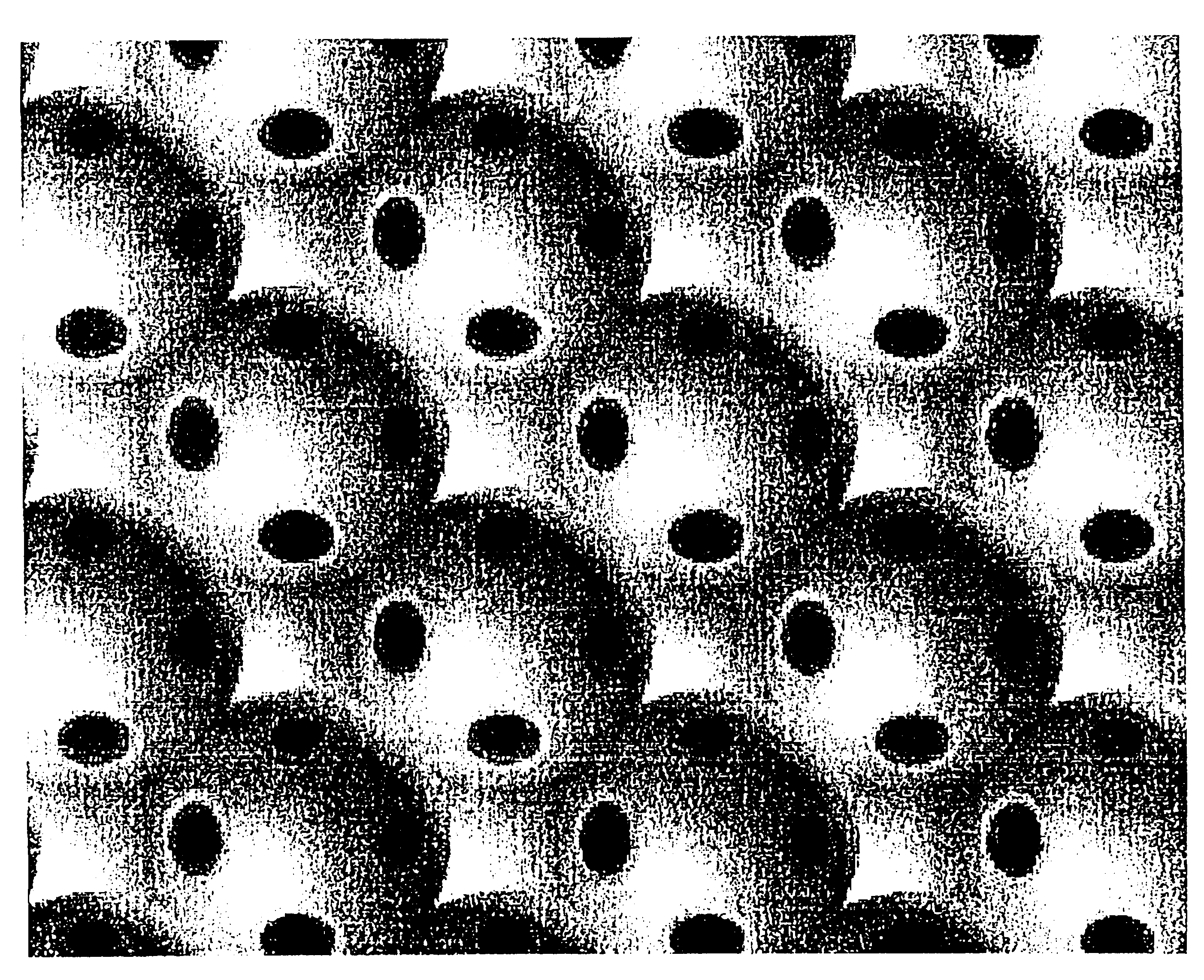
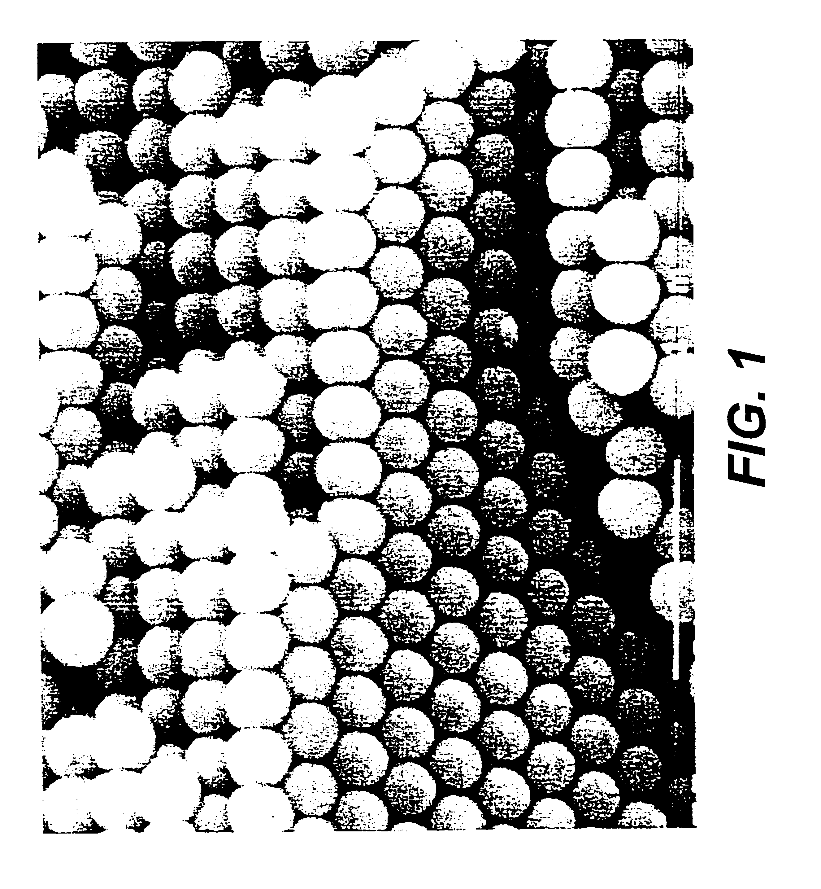
This example demonstrates the fabrication of a phenolic inverse opal by the templating of a sintered porous opal that has a periodic structure at optical wavelengths. FurCarb.RTM. Resin (187 g, LP-520, which is a furfuryl-based phenolic resin available from Great Lakes Chemical Corporation, P. O. Box 2200, West Lafayette, Ind. 47906) was vigorously stirred for ten minutes at room temperature after adding four drops of hydrochloric acid (37.5 wt %, Fisher) as the catalyst for polymerization. A piece of sintered porous opal (FIG. 1) composed of 250 nm SiO.sub.2 spheres was placed into a small Teflon coated aluminum cup containing about 1.5 gm of the above resin containing HCl catalyst. After two days at room temperature, during which time the resin infiltrated the opal, the resin was cured in an oven for three days at 80.degree. C., two days at 100.degree. C., and finally two days at 130.degree. C. The cured resin was black. After removing the cured resin around the resin-infiltrated ...

example 2

This example demonstrates the intense diffraction-based coloration of the polymer inverse opal and the switching of coloration. A piece of the phenolic inverse opal was prepared according to the previous example. It showed a brownish light-blue color. This inverse opal was broken into four pieces, which were placed in hexane, ethanol, acetone, and water, respectively. The sample in hexane showed a bright green color. The one in acetone gave red, green, and yellow opalescence depending on the orientation of the sample region with respect to the incident light. The one in ethanol offered a light yellow-green color. The one in water did not substantially change its color from that of the liquid-free inverse opal. These differences in coloration in the different liquids are attributed to the difference between the refractive indices of these liquids (which are 1.375, 1.359, 1.357, and 1.333 for hexane, ethanol, acetone, and water, respectively).

example 3

The samples comprising cured phenolic resin in SiO.sub.2 opal were prepared according to the procedure in Example 1. These samples were then embedded in the powder of the cured resin and carbonized under argon using the following thermal process. The sample temperature was increased from room temperature to 750.degree. C. in five hours, maintained at 750.degree. C. for three hours, and then cooled down to room temperature without temperature control. After the samples were treated with an oxygen-plasma for 5 minutes, they showed opalescence on a dark-black background. Then the samples were further treated with hydrofluoric acid for 2.5 hours, repeatedly washed with water, and dried over anhydrous CaSO.sub.4. This overall process, used for removing the silica spheres decreased the sample weight by about 87 to 90%, but did not cause a change in sample size and shape. This sample was opalescent and did not noticeable change coloration when immersed in liquids having various refractive ...


PUM

PropertyMeasurementUnit
Fractionaaaaaaaaaa
Fractionaaaaaaaaaa
Thicknessaaaaaaaaaa

Abstract

This invention relates to processes for the assembly of three-dimensional structures having periodicities on the scale of optical wavelengths, and at both smaller and larger dimensions, as well as compositions and applications therefore. Invention embodiments involve the self assembly of three-dimensionally periodic arrays of spherical particles, the processing of these arrays so that both infiltration and extraction processes can occur, one or more infiltration steps for these periodic arrays, and, in some instances, extraction steps. The product articles are three-dimensionally periodic on a scale where conventional processing methods cannot be used. Articles and materials made by these processes are useful as thermoelectrics and thermionics, electrochromic display elements, low dielectric constant electronic substrate materials, electron emitters (particularly for displays), piezoelectric sensors and actuators, electrostrictive actuators, piezochromic rubbers, gas storage materials, chromatographic separation materials, catalyst support materials, photonic bandgap materials for optical circuitry, and opalescent colorants for the ultraviolet, visible, and infrared regions.

Description

1. Field of the InventionThis invention relates to processes for the synthesis of three-dimensionally periodic structures and functional composites by the self-assembly of spheres, followed by one or more structure modification, infiltration, and extraction processes. These structures can be applied as thermoelectrics and thermionics, electrochromic display elements, low dielectric constant electronic substrate materials, electron emitters (particularly for displays), piezoelectric sensors and actuators, electrostrictive actuators, piezochromic rubbers, gas storage materials, chromatographic separation materials, catalyst support materials, photonic bandgap materials for optical circuitry, and opalescent colorants for the ultraviolet, visible, and infrared regions.2. Description of Related ArtThe art describes various means for fabricating articles with periodic structures that repeat on the scale of millimeters, such as by conventional machining methods. Methods are also available ...

Claims


Application Information

Patent Timeline
IPC IPC(8): C04B38/00C04B38/04C09B69/00G02B6/122G02F1/15B01J32/00B82B1/00C01B31/02C01B31/04C01B33/18C08J9/26C09C3/10C23C16/01C30B29/04
CPCB82Y20/00C04B38/0022G02B6/1225C09B69/00C04B38/045C04B35/52C04B35/522G02F2202/32C04B2111/92C04B2111/80G02B1/005
Inventor ZAKHIDOV, ANVARBAUGHMAN, RAYCUI, CHANGXINGKHAYRULLIN, ILYAS I.LIU, LO-MINUDOD, IGORSU, JIKOZLOV, MIKHAIL
Owner ALLIEDSIGNAL INC
Why Eureka
Try Eureka