Method of forming a rare-earth dielectric layer

a rare earth and dielectric layer technology, applied in the direction of polycrystalline material growth, semiconductor lasers, instruments, etc., can solve the problems of low availability, high cost, and material for the fabrication of integrated circuits that have not achieved commercial acceptance,

Active Publication Date: 2006-03-23
IQE
View PDF34 Cites 280 Cited by
  • Summary
  • Abstract
  • Description
  • Claims
  • Application Information

AI Technical Summary

Benefits of technology

[0023] The ability to produce single-phase layers is a distinguishing feature of the methods disclosed herein. These single-phase materials result in high-quality dielectric / semiconductor interfaces, such as are required for high-performance devices and circuits. Furthermore, single-phase rare-earth dielectric layers, such as can be formed using the methods described herein, do not suffer from a limitation on thickness, as exhibited in the prior art.

Problems solved by technology

It is notable that germanium, while otherwise very desirable as a material for the fabrication of integrated circuits, has not achieved commercial acceptance.
This is due to its high cost and low availability, which is a direct consequence of the defect-related low-yield of germanium substrates.
More specifically, as node-scaling of ULSI circuits is pushed further into the sub-micron regime, silicon dioxide becomes increasingly less attractive as an interlayer dielectric material (e.g., gate oxide, etc.).
In particular, as silicon-based interlayer dielectrics become extremely thin, fundamental problems arise, such as an increase in quantum mechanical tunneling current, a decrease in dielectric breakdown strength, and a decrease in reliability.
Furthermore, decreases in the thickness of silicon-based interlayer dielectrics in ULSI electronics will result in increases in capacitance, which cause concomitant increases in RC (interconnect) delays and cross talk.
This adversely impacts device speed and power dissipation.
A further issue with the silicon / silicon dioxide material system is that in conventional integrated-circuit processing, a rate-limiting and yield-limiting step is the production of a gate oxide of sufficient quality.
As ULSI technology continues to scale further into the sub-micron regime, it will become increasingly difficult and expensive to obtain gate oxides of the requisite quality.
Unfortunately, these materials do not naturally occur, nor can they be produced using prior-art growth techniques.
But these rare-earth oxides are ill-suited for high-performance integrated circuits since they do not exhibit some of the characteristics listed above.
In addition, the thickness to which many prior-art rare-earth dielectrics can be grown on silicon is limited.
Prior art rare-earth dielectric deposition techniques have been unsuccessful in controlling the stoichiometry and crystalline structure for realization of single domain, single crystal rare-earth dielectrics.
The inherent limitation of most prior art techniques is a lack of elemental control during deposition.
Alkaline-oxide deposition techniques are limited to depositing alkaline-oxide layers of approximately 10 monolayers on silicon, due to crystal relaxation and defect formation.
These alkaline-oxide films, therefore, provide insufficient utility as interlayer dielectric layers in high-performance silicon integrated circuits.
Continued scaling of ULSI into the sub-micron regime is also pushing the limits of the silicon substrate itself.
Although several variations of this technology exist, all are incapable of providing ultrathin active layers of sufficient quality for fully-depleted electronics.
In addition, the interface quality and impurity concentration of the buried oxide layers is insufficient to support high-performance integrated circuitry.
Finally, the complexity of wafer bonding processes used to produce SOI wafers is quite high, which leads to high costs.
For these reasons, among any others, the acceptance of SOI wafers by the semiconductor industry has been rather limited.

Method used


Image

  • Method of forming a rare-earth dielectric layer
  • Method of forming a rare-earth dielectric layer
  • Method of forming a rare-earth dielectric layer

Examples


example 1

FOR TECHNIQUE 1 DEPOSITION OF AN OXYGEN-MONOLAYER AS TEMPLATE LAYER 706

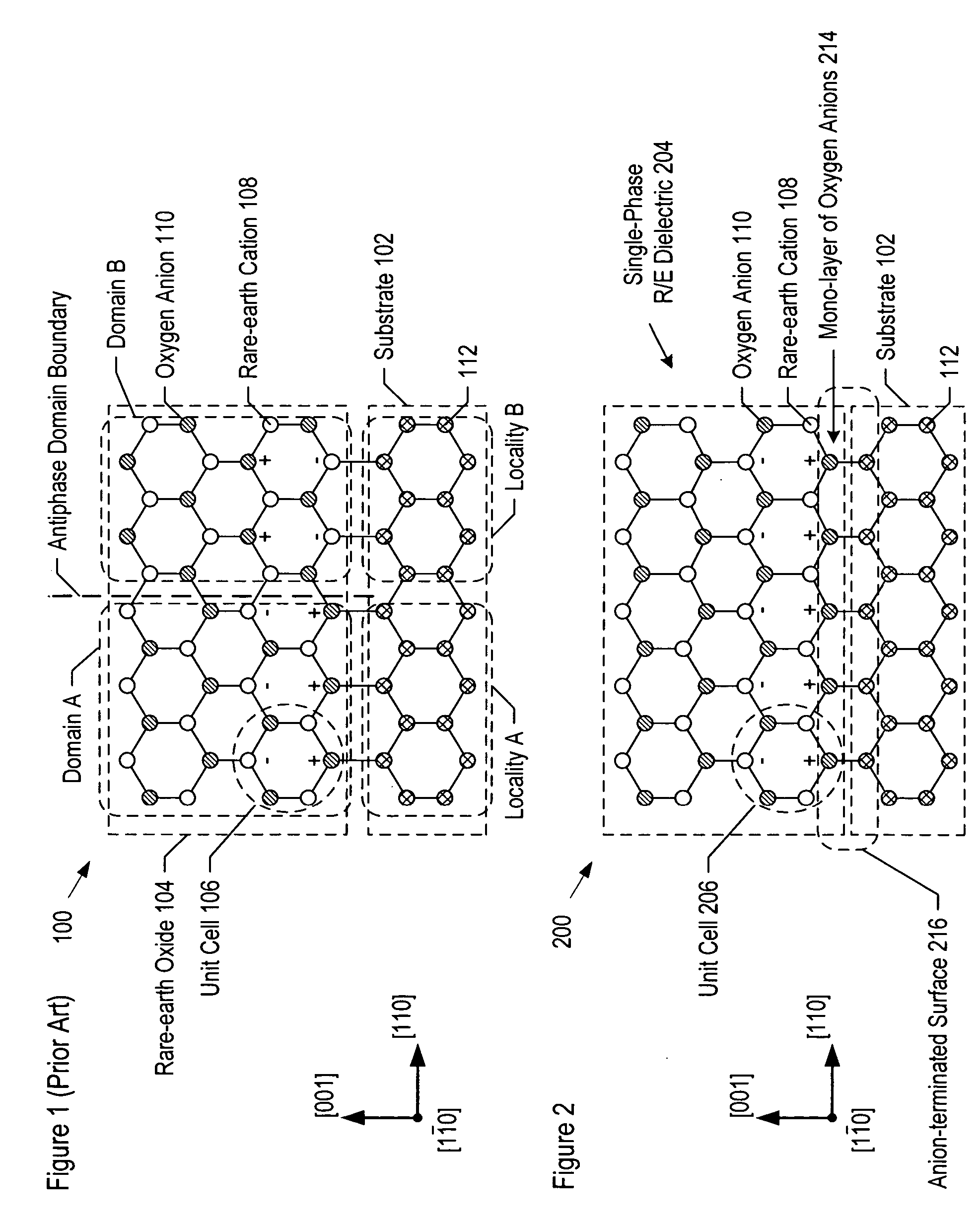
[0142] For this growth, template layer 706 comprised a monolayer of oxygen atoms, thereby providing an anion-terminated surface, and thereby providing an energetically-favorable bonding surface for cations (i.e., rare-earth metal cations). The oxygen atoms terminated the semiconductor (e.g., silicon) bonds that were available at the surface of wafer 702.

[0143] Template layer 706 was grown on wafer 702 at a temperature in the range of 300° C. to 500° C. and in an atmosphere of 10−7 Torr oxygen background pressure, consistent with operation 705. ALE was used to grow the template layer. In some other embodiments, the ALE is conducted at a temperature in the range of 500° C. to 700° C. and in an atmosphere of 10−8 Torr oxygen background pressure. In this example, as well as alternative embodiments, ultra-low beam pressure plasma sources are used for the production of atomic and metastable oxygen species.

example 2

FOR TECHNIQUE 1 DEPOSITION OF SILICON DIOXIDE AS TEMPLATE LAYER 706

[0144] In this example, template layer 706 comprised a few monolayers of silicon dioxide molecules, thereby providing an anion-terminated surface. Silicon dioxide was deposited using ALE, which was conducted at a temperature in the range of 300° C. to 500° C. and in an atmosphere of 10−7 Torr oxygen background pressure. In some embodiments, ALE is conducted at a temperature in the range of 500° C. to 700° C. and in an atmosphere of 10−8 Torr oxygen background pressure.

example 3

FOR TECHNIQUE 1 DEPOSITION OF A RARE-EARTH AS TEMPLATE LAYER 706

[0145] In this example, template layer 706 comprised 1-10 monolayers of erbium atoms, deposited on wafer 702 using ALE. Template layer 706, therefore, provided a cation-terminated surface which provides an energetically-favorable bonding surface for cations. Template layer 706 was formed using ALE to deposit erbium atoms. Growth conditions for erbium template layer 706 included a growth temperature in the range from 25° C. to approximately 700° C., at a maximum oxygen background pressure of 10−9 Torr.

[0146] Technique 2—Compensation with an Oxide or a Nitride

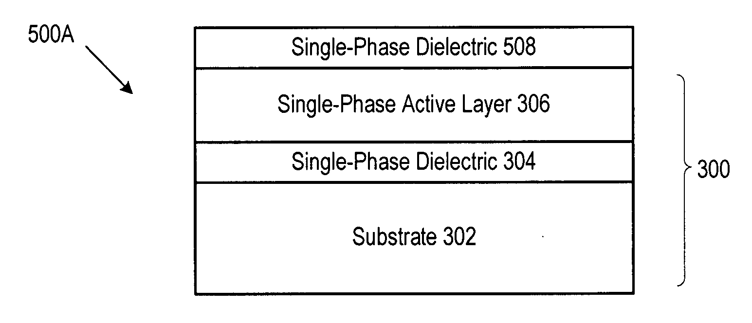
[0147]FIG. 8A depicts a composition that includes wafer 702 and oxy-nitride or nitride layer 804. In some embodiments, these layers collectively represent substrate 302 of composition 300 of FIG. 3. As described further below, oxy-nitride or nitride layer 804 provides a preferential growth surface for cations 108.

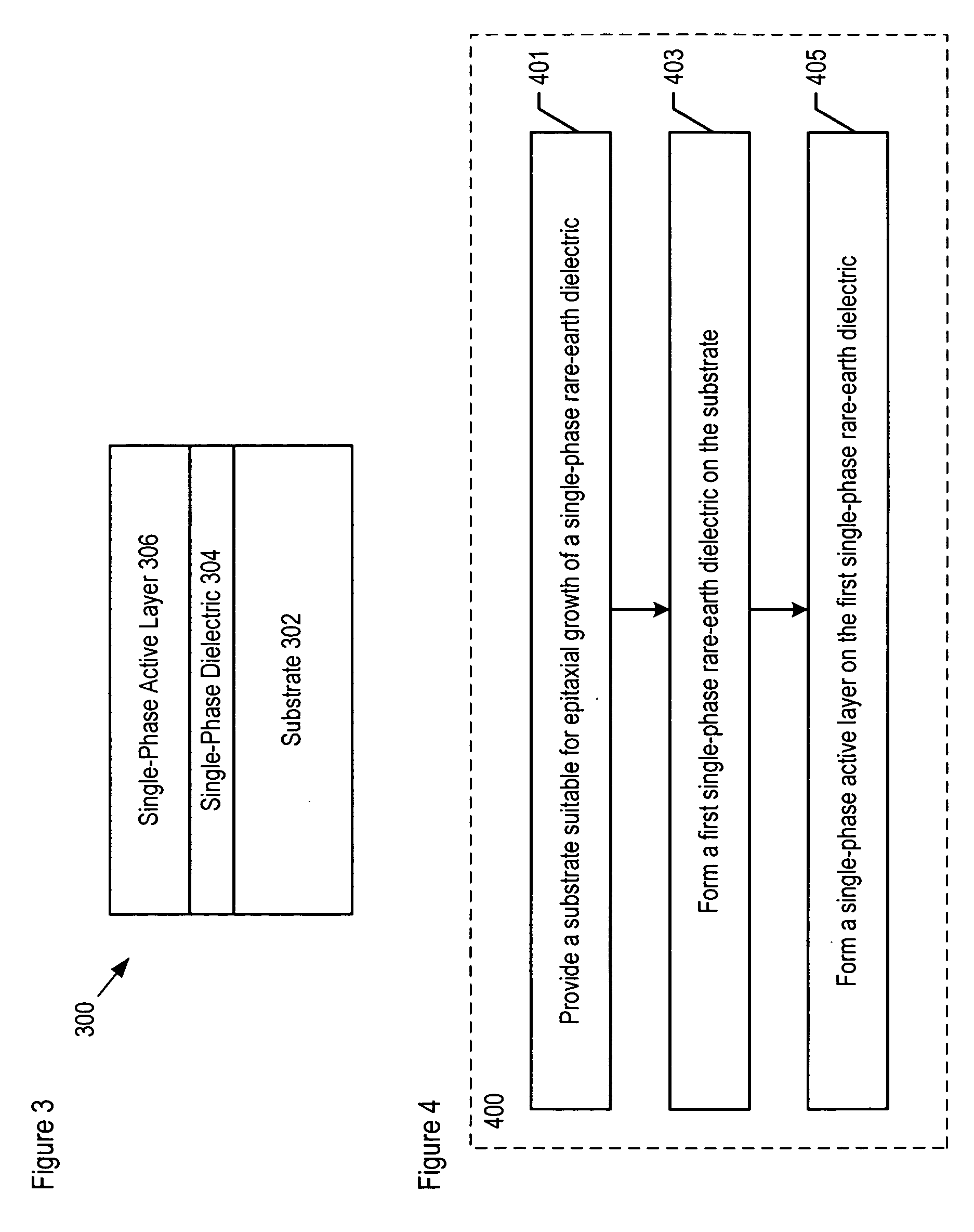
[0148]FIG. 8B depicts the details of operation 401 ...


PUM

PropertyMeasurementUnit
angleaaaaaaaaaa
atomic numberaaaaaaaaaa
thicknessaaaaaaaaaa

Abstract

Methods for forming compositions comprising a single-phase rare-earth dielectric disposed on a substrate are disclosed. In some embodiments, the method forms a semiconductor-on-insulator structure. Compositions and structures that are formed via the method provide the basis for forming high-performance devices and circuits.

Description

STATEMENT OF RELATED CASES [0001] This application is a continuation-in-part of co-pending U.S. patent application Ser. No. 11 / 025,693 filed on Dec. 28, 2004, which claims priority of provisional patent application U.S. Ser. No. 60 / 533,378 filed on Dec. 29, 2003. Furthermore, this case is related to U.S. patent application Ser. No. ______ Attorney Docket No. 367-015US, filed on even date herewith, and incorporated by reference herein.FIELD OF THE INVENTION [0002] The present invention relates to compositions for electronic devices and integrated circuits. BACKGROUND OF THE INVENTION [0003] Silicon is the material of choice for the fabrication of ultra large scale integrated (“ULSI”) circuits. This is due, in large part, to the fact that silicon is the only semiconductor substrate material that can be formed as large-diameter wafers with sufficiently low defect density. Also, silicon forms a high-quality oxide (i.e., silicon dioxide), and the quality of the silicon / silicon dioxide in...

Claims


Application Information

Patent Timeline
Patent Type & Authority Applications(United States)
IPC IPC(8): C30B25/00C30B28/12C30B28/14C30B23/00
CPCB82Y20/00H01S2301/173C30B25/205C30B29/14C30B29/16C30B29/38C30B29/40G02B6/1225G02B6/125H01L21/3141H01L21/3143H01L21/31604H01L21/31645H01L27/15H01L29/26H01L29/51H01L33/34H01S3/0604H01S3/0627H01S3/1603H01S3/1628H01S5/0261H01S5/18341H01S5/18369C30B25/14H01L21/022H01L21/0228
Inventor ATANACKOVIC, PETAR
Owner IQE
Why Eureka
Try Eureka