Stent with angled struts and crowns

a stent and strut technology, applied in the field of stents with angled struts, can solve the problems of reducing increasing the risk of strut/crown lifting and stent retention, and reducing the ability of the struts and crowns to open (referred to as overexpansion), so as to achieve similar radial strength, reduce the radial strength of the stent, and reduce the risk o

Pending Publication Date: 2022-01-27
MEDTRONIC VASCULAR INC
View PDF4 Cites 2 Cited by
  • Summary
  • Abstract
  • Description
  • Claims
  • Application Information

AI Technical Summary

Benefits of technology

[0004]The design of a stent must balance several characteristics. For example, and not by way of limitation, characteristics such as stent distortion, radial strength, overexpansion, crossing profile, flexibility, strut / crown lift, retention, metal to artery ratio, drug load, and retention are some of the many characteristics used to drive optimization and design decisions. For example, using thinner profile struts while keeping other variables the same for a given design, the radial strength of the stent decreases and risk of strut / crown lifting and stent retention increase. If the thinner profile strut is paired with a decrease in strut lengths to maintain a similar radial strength, then the ability of the struts and crowns to open (referred to as overexpansion) is compromised. Thinner struts are generally desirable for improved flexibility, deliverability, and a prevailing belief that thinner struts improve lesion healing. Strut / crown lifting (or stent lifting) is when either a crown or strut or multiple crowns and struts are lifted out of plane which would give an appearance those crowns / struts being lifted away from the delivery system. This is seen as deformation of the crowns / struts outward in the radial direction. Stent distortion is deformation of the stent along the long axis of the stent.

Problems solved by technology

For example, using thinner profile struts while keeping other variables the same for a given design, the radial strength of the stent decreases and risk of strut / crown lifting and stent retention increase.
If the thinner profile strut is paired with a decrease in strut lengths to maintain a similar radial strength, then the ability of the struts and crowns to open (referred to as overexpansion) is compromised.

Method used


Image

  • Stent with angled struts and crowns
  • Stent with angled struts and crowns
  • Stent with angled struts and crowns

Examples


Embodiment Construction

[0038]Specific embodiments of the present invention are now described with reference to the figures, wherein like reference numbers indicate identical or functionally similar elements.

[0039]The following detailed description is merely exemplary in nature and is not intended to limit the invention or the application and uses of the invention. Although the description of the invention is in the context of treatment of blood vessels, the invention may also be used in any other body passageways where it is deemed useful. Furthermore, there is no intention to be bound by any expressed or implied theory presented in the preceding technical field, background, brief summary or the following detailed description.

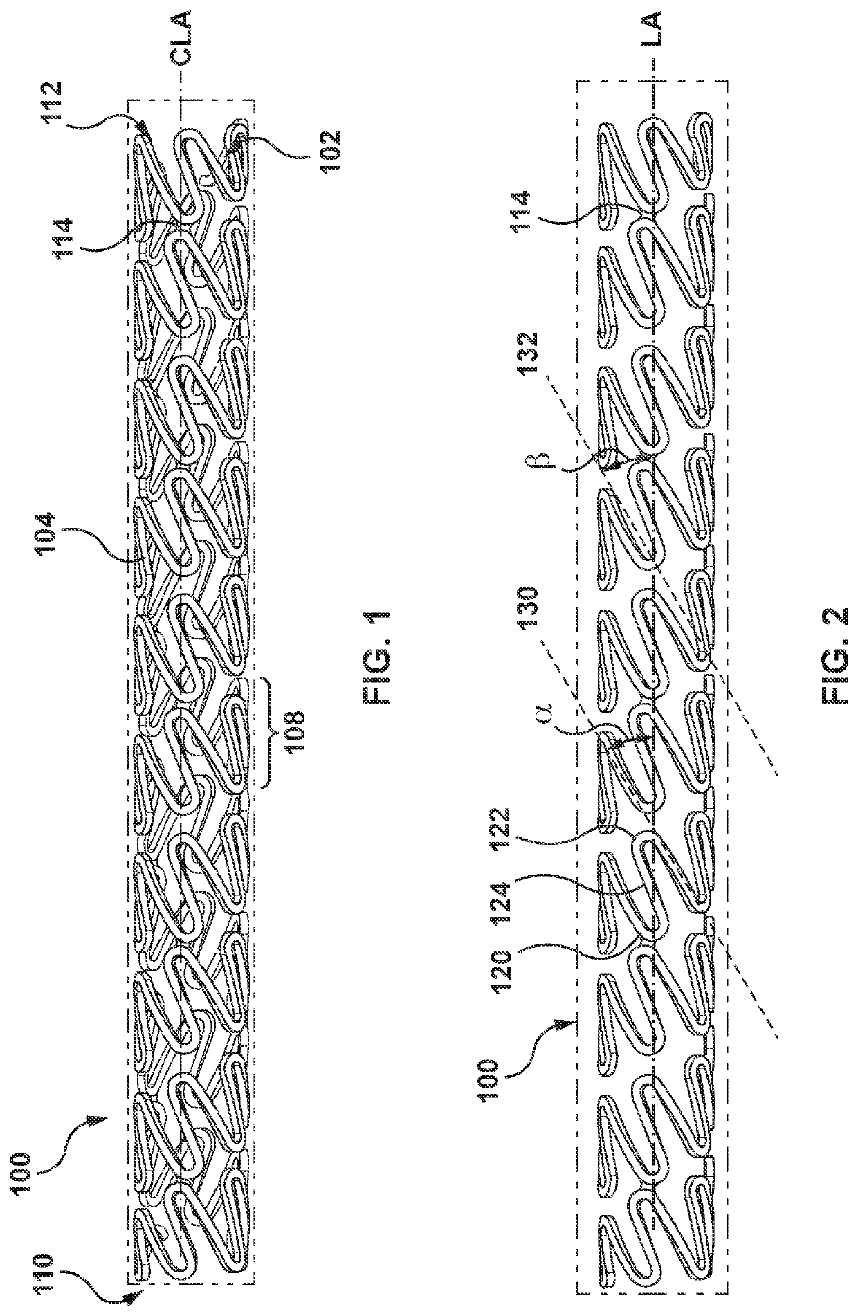
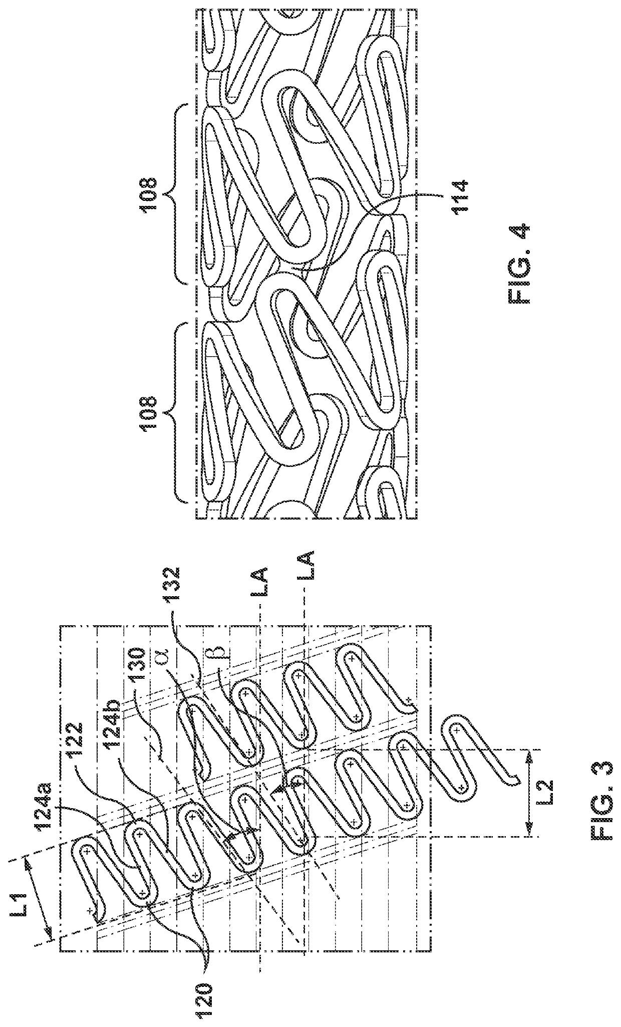
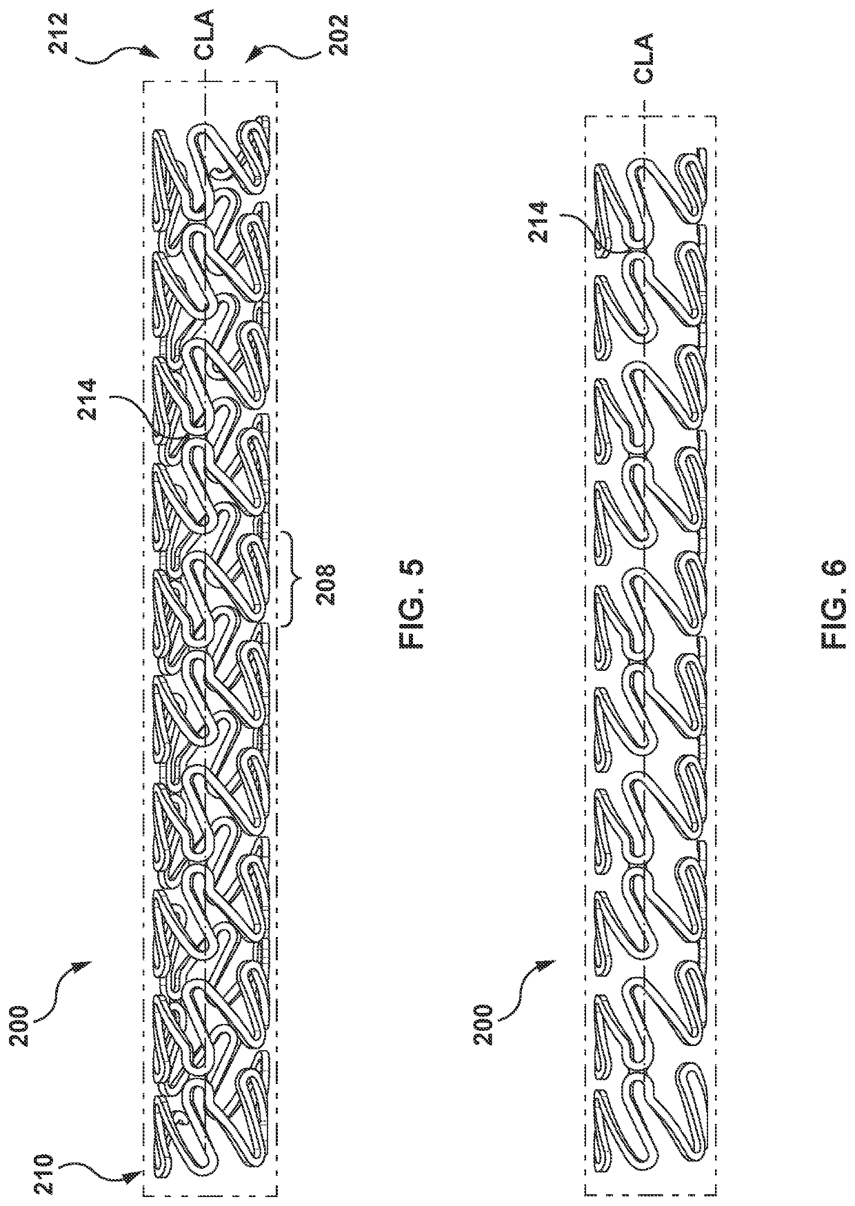
[0040]The term “continuous wire stent” as used herein means a stent form by from a wire that is bent into a waveform and helically wrapped around a central longitudinal axis to form a tube. Stents that are formed, e.g., by laser cutting a tube to removed portions such that the portio...


PUM


Abstract

A stent in a radially compressed configuration includes a plurality of first outer crowns and a plurality of second outer crowns, each of the first outer crowns and the second outer crowns connected by a strut of a plurality of struts. The plurality of first outer crowns and the plurality of second outer crowns are disposed at a crown angle in the range of about 15 degrees to about 35 degrees, the crown angle being defined by a line extending through a midpoint of a crown of the plurality of first outer crowns or the plurality of second outer crowns through a center of radius of the crown with respect to a line that is parallel to a central longitudinal axis of the stent.

Description

CROSS-REFERENCE TO RELATED APPLICATIONS[0001]This application claims the benefit of the filing date of U.S. Provisional Application No. 63 / 056,166, filed Jul. 24, 2020, the contents of which are incorporated herein by reference in their entirety.FIELD OF THE INVENTION[0002]This invention generally relates to endoluminal prostheses or stents. More specifically, the invention relates to stents with angled struts.BACKGROUND OF THE INVENTION[0003]A stent is a type of endoluminal prosthesis. Stents are generally tubular open-ended structures providing support for damaged, collapsing, or occluded blood vessels. They are radially expandable from a radially compressed configuration for delivery to the affected vessel site to a radially expanded configuration when deployed at the affected vessel treatment site, with the radially expanded configuration having a larger diameter than the radially compressed configuration. Stents are generally inserted in the radially compressed configuration an...

Claims


Application Information

Patent Timeline
Patent Type & Authority Applications(United States)
IPC IPC(8): A61F2/915
CPCA61F2/915A61F2220/0058A61F2002/91525A61F2/88A61F2002/91558
Inventor ASKARI, SYEDBLISS, RICHARD
Owner MEDTRONIC VASCULAR INC
Why Eureka
Try Eureka