Supercharge Your Innovation With Domain-Expert AI Agents!

Circumferential Seal Assembly with Adjustable Seating Forces

Active Publication Date: 2022-01-27
STEIN SEAL
View PDF18 Cites 0 Cited by
  • Summary
  • Abstract
  • Description
  • Claims
  • Application Information

AI Technical Summary

Benefits of technology

The invention provides a seal assembly that minimizes leakage and heating in a turbine engine operating at high shaft speeds and pressures. It reduces seating forces and contact forces, which reduces oil coolant requirements and coolant needs. The seal assembly also self-adjusts to balance the force at the sealing surface. Overall, the invention improves the efficiency and reliability of the turbine engine.

Problems solved by technology

Mixture between the liquid and the gas within one compartment could compromise the integrity of the sealing assembly thereby adversely effecting performance and function of a gas turbine.
High pressure and temperatures are problematic in that it is more challenging to properly balance the forward face force FF with respect to both the aft face force FA and the spring force FS and both the inward radial force FI and the spring force FG with respect to the outward radial force FO over a wider range of operating conditions.
The resulting imbalance effectively pins the circumferential seal 1 onto and against the face sealing surface 11 and the radial sealing surface 19 causing excessive wear to and heating of the circumferential seal 1.
Wear and heating are further problematic in turbine engines that derive greater performance and higher efficiency via higher shaft speeds.
The end results could include an engine fire and / or flow conditions in the direction of the sump that blow lubricating oil away from the seal and the sealing surface.

Method used


Image

  • Circumferential Seal Assembly with Adjustable Seating Forces
  • Circumferential Seal Assembly with Adjustable Seating Forces
  • Circumferential Seal Assembly with Adjustable Seating Forces

Examples


Embodiment Construction

[0071]Reference will now be made in detail to several embodiments of the invention that are illustrated in the accompanying drawings. Wherever possible, same or similar reference numerals are used in the drawings and the description to refer to the same or like parts. The drawings are in simplified form and are not to precise scale.

[0072]While features of various embodiments are separately described, it is understood that such features are combinable to form other embodiments.

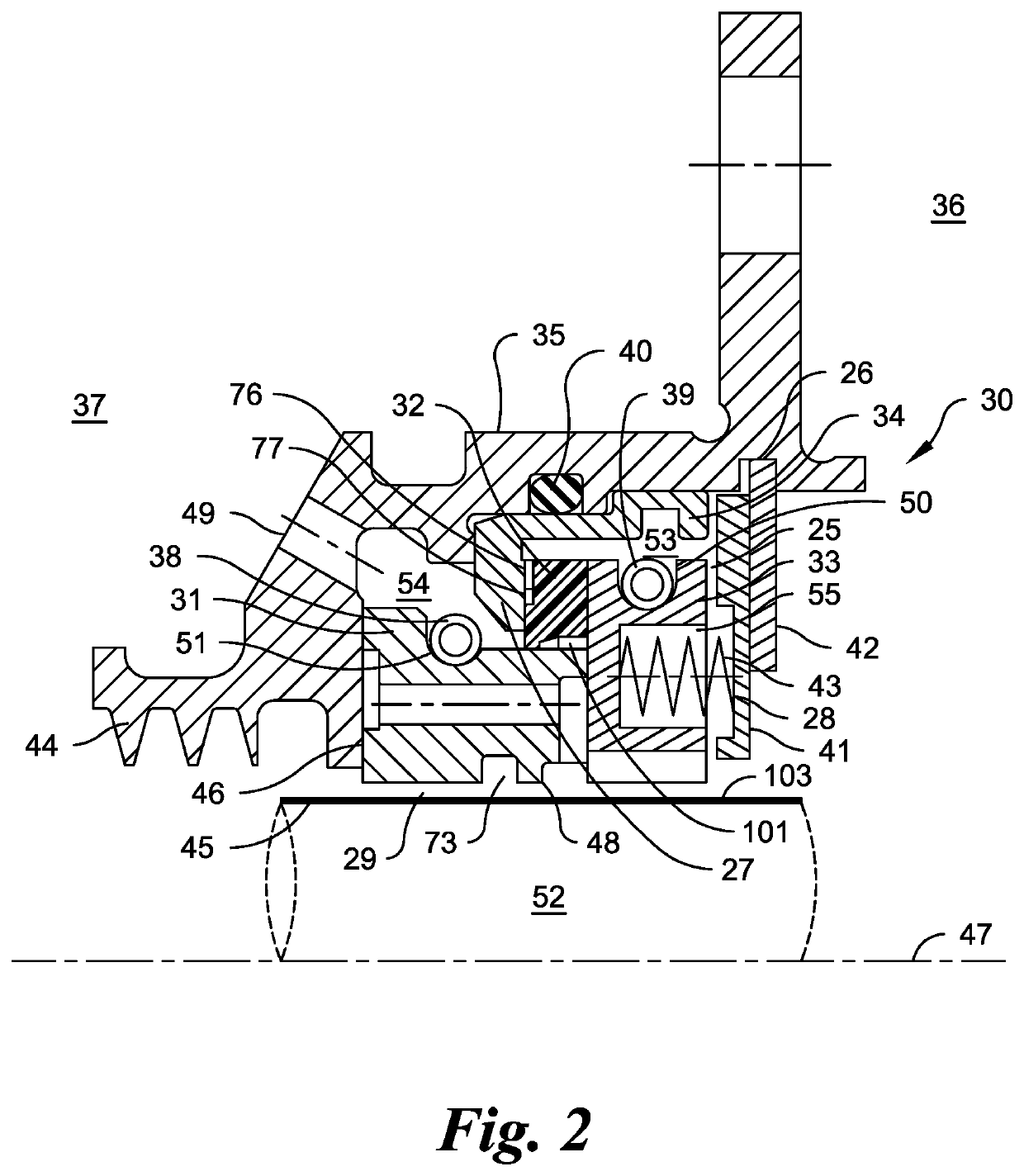
[0073]Referring now to FIG. 2, a circumferential seal assembly 30 is shown disposed within a housing 35 about a rotatable element 52. The circumferential seal assembly 30 generally comprises a primary sealing ring 31, a second sealing ring 32, a third sealing ring 33, and an insert 34. Components for the circumferential seal assembly 30 are secured within the housing 35 preferably via securing means understood in the art, non-limiting examples including a back plate 41 and a retaining ring 42. Components of the...


PUM


Abstract

A circumferential seal assembly for use between a higher pressure side and a lower pressure side is presented. The seal assembly includes a primary sealing ring, a second sealing ring, a third sealing ring, and an insert. The segmented primary sealing ring sealingly engages both a face sealing surface along a housing and a radial sealing surface along a rotatable element. The insert is disposed within and directly contacts the housing. The second sealing ring is adjacent to the primary sealing ring and sealingly engages both the primary sealing ring and the insert. The segmented third sealing ring contacts and sealingly engages the primary sealing ring opposite the housing. The insert, the second sealing ring, and the third sealing ring cooperate to form a first cavity adjacent to the second sealing ring and the third sealing ring. The primary sealing ring, the second sealing ring, the insert, and the housing cooperate to form a second cavity adjacent to the primary sealing ring. The insert and the second sealing ring separate the first cavity from the second cavity.

Description

CROSS REFERENCE TO RELATED APPLICATIONS[0001]This application is a continuation of U.S. patent application Ser. No. 16 / 491,189 filed Sep. 5, 2019 entitled Improved Circumferential Seal Assembly with Adjustable Seating Forces which is a National Stage entry of PCT Application No. PCT / US2017 / 030834 filed May 3, 2017 entitled Improved Circumferential Seal Assembly with Adjustable Seating Forces wherein both applications are hereby incorporated herein in their entirety by reference thereto.GOVERNMENT SPONSORED RESEARCH AND DEVELOPMENT[0002]None.BACKGROUND OF THE INVENTION1. Field[0003]The invention generally relates to a circumferential seal assembly for controlling flow of a fluid between adjoining compartments within a turbine engine and more particularly is concerned, for example, with minimizing flow across a sealing surface along a rotatable shaft or a runner that extends into one compartment with a fluid at a higher pressure and into another compartment with another fluid at a low...

Claims


Application Information

Patent Timeline
IPC IPC(8): F01D11/00F16J15/24F16J15/44
CPCF01D11/003F16J15/24F05D2240/55F05D2220/32F16J15/442F16J15/26
Inventor GARRISON, GLENN M.
Owner STEIN SEAL
Features
  • R&D
  • Intellectual Property
  • Life Sciences
  • Materials
  • Tech Scout
  • Unparalleled Data Quality
  • Higher Quality Content
  • 60% Fewer Hallucinations
Learn More