Speaker diaphragm

a diaphragm and speaker technology, applied in the field of speaker diaphragms, can solve the problems of sound pressure drop, difficulty in ensuring rigidity of the diaphragm, breakage mode of the diaphragm, etc., to reduce the rate of overall mass increase, improve the rigidity of the cone part, and increase the rigidity of the body member

Active Publication Date: 2022-02-03
FOSTER ELECTRIC CO LTD
View PDF0 Cites 0 Cited by
  • Summary
  • Abstract
  • Description
  • Claims
  • Application Information

AI Technical Summary

Benefits of technology

[0028]The embodiments and aspects of the present invention improve the rigidity of the cone part without changing the shape of the body member including the center cap part and the cone part on the outer periphery of the center cap part by joining the ring member to the cone part. This allows for management of a uniform thickness of the cone part of the body member in the circumferential direction and an increase in the rigidity of the body member even in a configuration in which the body member is thin and lightweight. This also reduces the rate of overall mass increase despite the configuration in which the ring member is joined to the cone part. Thus, the sound pressure is kept from decreasing and decaying in a high frequency range.
[0029]The increase in the rigidity of the outer periphery of the body member, which in other words is the cone part, allows for a shift of a breakup mode point toward a higher frequency range. This keeps the sound pressure from decreasing in a high frequency range, achieving an improvement in the frequency characteristics.
[0030]The cone part has a rising shape that rises frontward (toward the front of the speaker), allowing for easy radial positioning (centering) and easy production. Such a rising shape also advantageously improves the rigidity.

Problems solved by technology

This shape constraint makes it difficult to ensure rigidity of the diaphragm, which includes cellulose as a main material, and causes breakup mode in the diaphragm.
Thus, the sound pressure decreases and frequency characteristics degrade.
However, even in the case of the diaphragm including the integrated center cap and cone parts, the sound pressure decays in a high frequency range due to breakup mode.
A resonance point being low and being in a frequency band to be reproduced poses an issue in the reproduction.
This leads to an excessive mass increase and a decrease in the sound pressure.
Furthermore, increasing the total height results in an increase in the size.
This affects the wear comfort and hinders the achievement of a desired design.
Production of a diaphragm having such a configuration therefore involves complicated processes because relative positioning of parts and members is difficult.
Since the ring-shaped member of the diaphragm disclosed in Patent Document 3 has to have a dome shape and an increased thickness, production of the diaphragm is complicated.
Furthermore, an increase in the thickness accompanies a mass increase, causing a decrease in the sound pressure.
This gives rise to a change in the shape of the center cap part, and production of such a diaphragm is complicated.

Method used


Image

  • Speaker diaphragm
  • Speaker diaphragm
  • Speaker diaphragm

Examples


Embodiment Construction

[0037]The following describes a preferred embodiment of the present invention with reference to the drawings.

[0038]A speaker diaphragm according to an embodiment of the present invention is mainly applied to headphones. The speaker diaphragm is preferably made from a paper material and is of free-edge type.

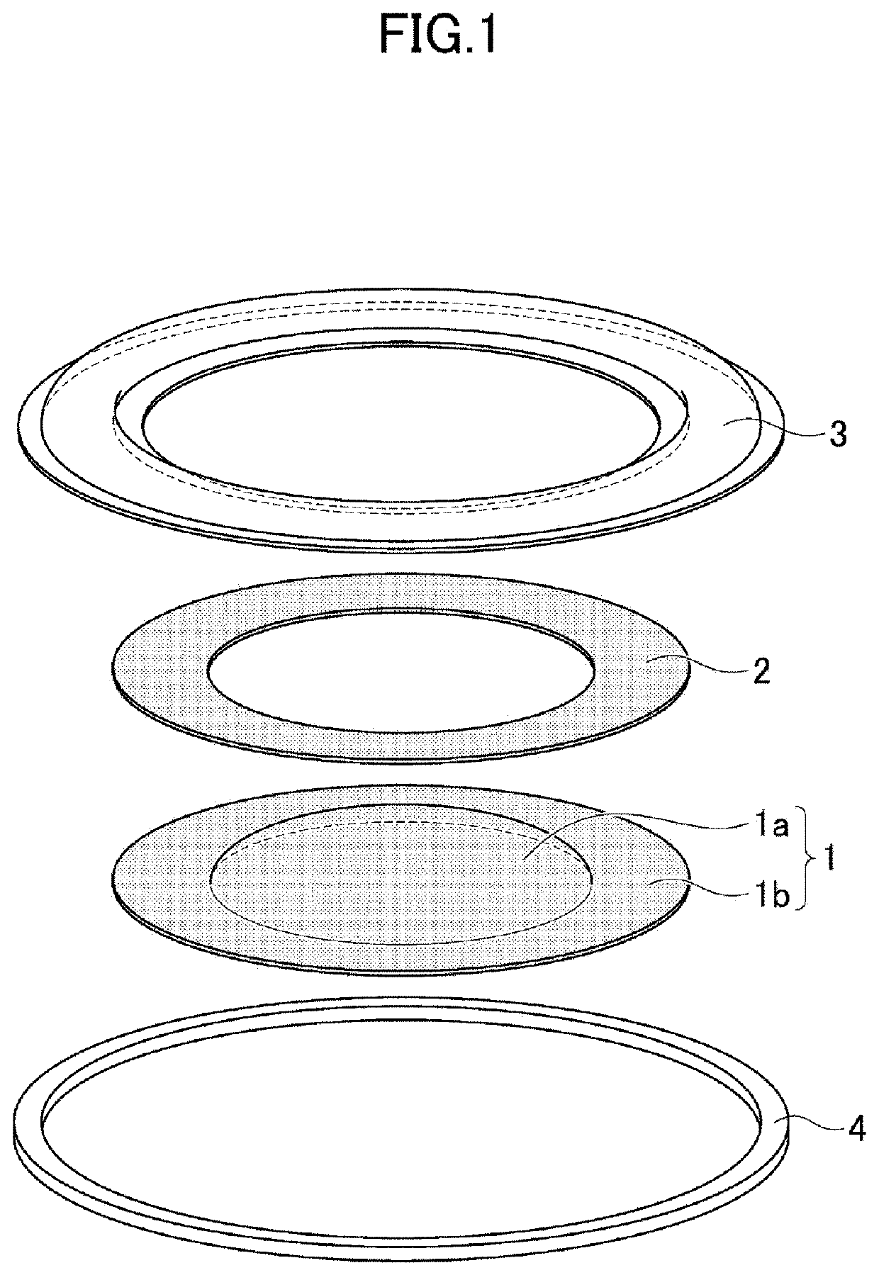
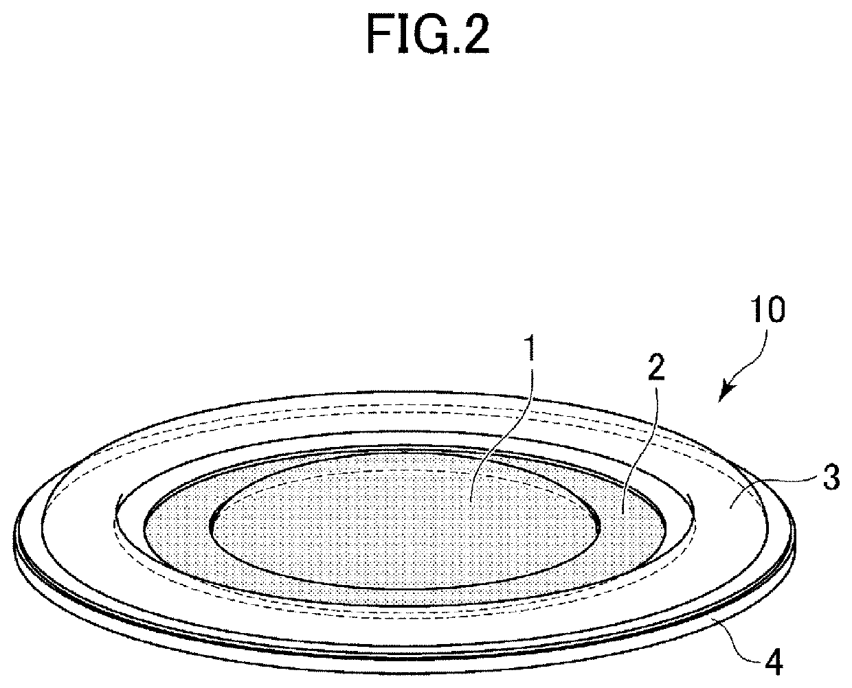
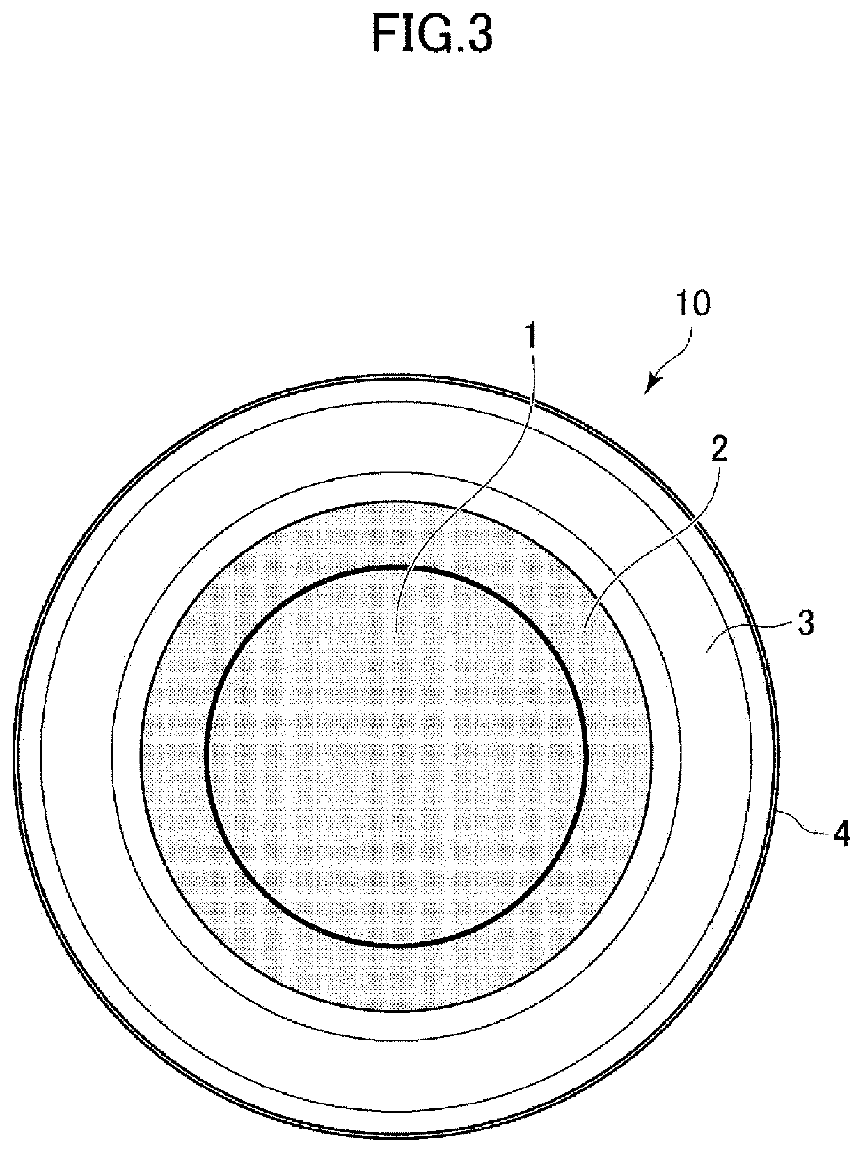
[0039]In FIG. 1, reference character 1 denotes a body member of a diaphragm. The body member 1 includes a dome-shaped center cap part 1a and a flange-shaped cone part 1b bulging radially outward from the outer peripheral edge of the center cap part. Reference character 2 denotes a ring member having substantially the same shape as the cone part 1b. The ring member 2 and the cone part 1b are stacked on one another and integrated by being bonded together with a urethane or rubber-based adhesive through heat-pressing. The ring member 2 is paper that is formed separately from the body member 1 into a simple flat plate shape that allows for easy production. By forming the ring member 2...


PUM


Abstract

The present invention is configured such that, a ring member is bonded to a cone section formed on the outer circumference of a vibration plate body, and the inner circumferential section of an edge is bonded to the outer circumference section of the ring member or the cone section. Thus, the stiffness is increased without requiring a change in the shape of the vibration plate body, that is, the stiffness is improved without causing an increase in the weight of the vibration plate body, and a degradation in acoustic pressure at high frequencies is prevented.

Description

CROSS-REFERENCE TO RELATED APPLICATION[0001]This application is the § 371 National Stage of International Application No. PCT / JP2019 / 035952, filed on Sep. 12, 2019, which claims the benefit of Japanese Patent Application Serial No. 2018-173208, filed on Sep. 18, 2018, the contents of which applications are hereby incorporated by reference in their entirety.FIELD OF THE INVENTION[0002]The present disclosure relates to a speaker diaphragm suitable for use in headphones.BACKGROUND OF THE INVENTION[0003]A speaker for use in a headphone is desired to be small and thin by itself to meet wear comfort and design demands of the headphone. Accordingly, a diaphragm for use in the speaker is also desired to be thin. For this reason, a dome-shaped diaphragm is subject to the constraint that the total height of a dome portion thereof has to be low. Such a diaphragm therefore has lower rigidity.[0004]Existing materials of diaphragms are diverse and include novel materials and synthetic polymers su...

Claims


Application Information

Patent Timeline
Patent Type & Authority Applications(United States)
IPC IPC(8): H04R1/10H04R7/12H04R7/18
CPCH04R1/1075H04R7/18H04R7/127H04R7/22H04R2307/029H04R9/06H04R9/045H04R1/10
Inventor YAMAKI, SHINTAROMATSUMURA, TAKASHIHORIGUCHI, MINORU
Owner FOSTER ELECTRIC CO LTD
Why Eureka
Try Eureka