
Method for protection against fretting fatigue by compound modification via laser shock peening and coating lubrication

a technology of coating lubrication and compound modification, applied in the field of surface protection, can solve the problems of reducing fatigue strength or life, hot spot, and common use of immovable fittings such as riveted connections, bolted connections, etc., and achieve the effect of further improving the fretting fatigue resistance of a componen

Pending Publication Date: 2022-02-17
DALIAN UNIV OF TECH +1
View PDF8 Cites 5 Cited by
  • Summary
  • Abstract
  • Description
  • Claims
  • Application Information

AI Technical Summary

Benefits of technology

The present patent provides a method for protecting against fretting fatigue by combining laser shock peening and coating lubrication. This method allows for improved fretting fatigue behavior of a material by reinforcing its surface through residual compressive stress, coating lubrication, and surface micro-pit texturing with a synergistic effect. The method also reduces surface friction, prolongs life during fretting fatigue propagation, and increases wear time of the lubricating coating. The method creates an antifriction laser shock peening textured surface and uses the accessory micro-pit styling effect of the laser shock peening.

Problems solved by technology

In machinery manufacturing, components and parts commonly used in immovable fitting such as riveted connection, bolted connection and mortise and tenon connection are prone to fretting fatigue in vibration environment.
A tiny displacement (on the micron scale) of a contact surface of a part may cause friction and wear of the contact surface, resulting in greatly reduced fatigue strength or life.
Compound modification is based on a combination of two or three protection techniques to achieve a synergistic effect of multiple reinforcing factors, and is not only a hot spot but also a difficult problem in global academic circles.
This is because a compound modification process usually involves a combination of two technical measures, which may easily arouse performance interference or conflict.

Method used


Image

  • Method for protection against fretting fatigue by compound modification via laser shock peening and coating lubrication
  • Method for protection against fretting fatigue by compound modification via laser shock peening and coating lubrication

Examples


example 1

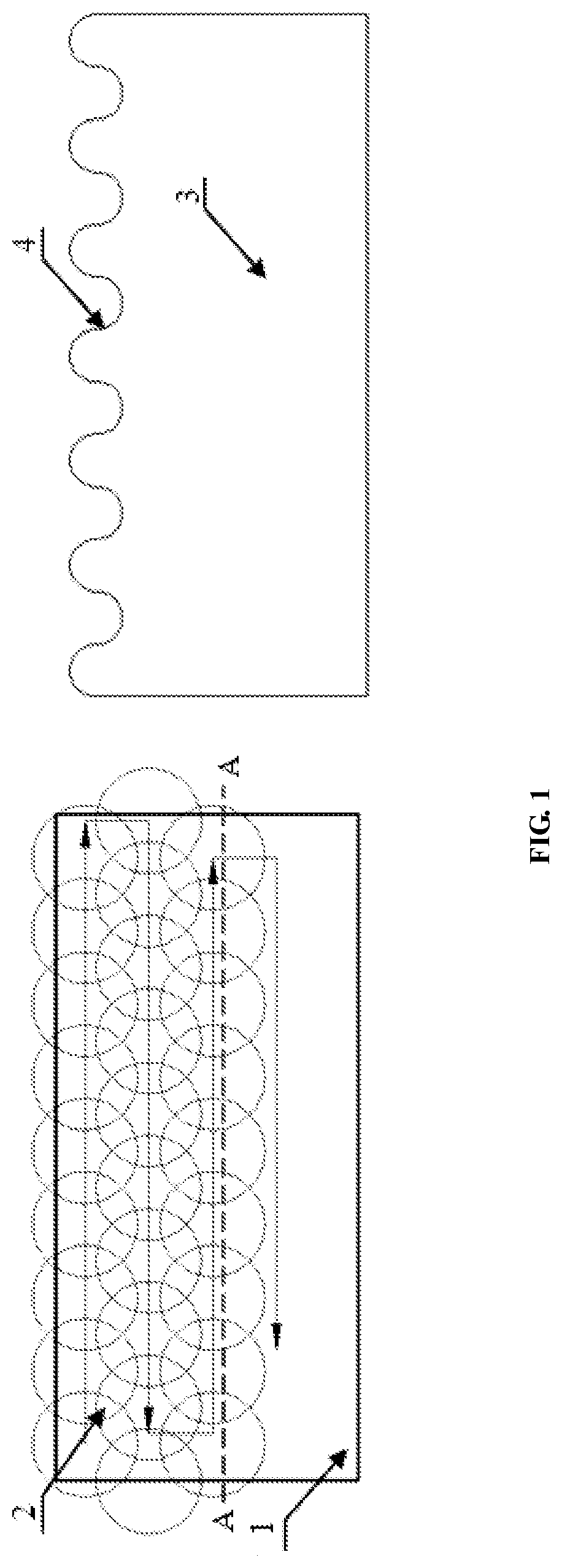
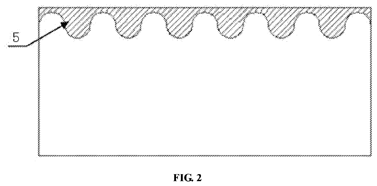
[0028]As shown in FIG. 1 and FIG. 2, the present disclosure provides a method for protection against fretting fatigue by compound modification via laser shock peening and coating lubrication. The laser shock peening and the coating lubrication were combined to provide a novel integrated surface protection technique, which specifically included the following steps.

[0029]The surface of micro-pits (micro-pit texture) distributed into a regular array was firstly formed in a surface of a metal material by using laser shock peening, with a single micro-pit having a diameter of 1 to 10 mm and a depth of 1 to 20 μm; and the micro-pits were then coated with a lubricant by coating preparation.

[0030]Further, the laser shock peening was carried out by partial overlapping of individual spots along a laser shock path, where the spot was circular or square and an overlapping rate of the spots was 10% to 50%. In the present disclosure, the coverage of the laser shock peening on the surface of the s...


PUM

PropertyMeasurementUnit
depthaaaaaaaaaa
diameteraaaaaaaaaa
thickaaaaaaaaaa

Abstract

The present disclosure provides a method for protection against fretting fatigue by compound modification via laser shock peening and coating lubrication, where a group of micro-pits distributed into a regular array is firstly formed in a surface of a metal material by using laser shock peening, with a single micro-pit having a diameter of 1 to 10 mm and a depth of 1 to 20 μm; and the micro-pits are then coated with a lubricant by coating preparation. Based on the micro-pit styling feature and surface residual compressive stress introducing feature of the laser shock peening, with compound modification by surface texturing via the laser shock peening and coating lubrication, the surface of the material can be reinforced by residual compressive stress, coating lubrication and surface micro-pit texturing with a synergistic effect, thus allowing for improved fretting fatigue behavior of the material.

Description

CROSS REFERENCE TO RELATED APPLICATION[0001]This patent application claims the benefit and priority of Chinese Patent Application No. 202010814090.3 filed on Aug. 13, 2020, the disclosure of which is incorporated by reference herein in its entirety as part of the present application.TECHNICAL FIELD[0002]The present disclosure belongs to the technical field of surface protection, relates to a method for surface modification of a structural metal part with the purpose of improving the fretting fatigue behavior of a material, and in particular, to a method for protection against fretting fatigue by compound modification via laser shock peening and coating lubrication.BACKGROUND ART[0003]In machinery manufacturing, components and parts commonly used in immovable fitting such as riveted connection, bolted connection and mortise and tenon connection are prone to fretting fatigue in vibration environment. A tiny displacement (on the micron scale) of a contact surface of a part may cause fr...

Claims


Application Information

Patent Timeline
Patent Type & Authority Applications(United States)
IPC IPC(8): C21D10/00B23K26/356
CPCC21D10/005B23K26/356C23C4/134C23C4/02C23C4/04C23C4/08C23C24/04C25D5/34
Inventor FU, XUESONGLI, ZHIQIANGCAO, ZIWENLUO, MAOZHONGZHOU, WENLONGCHEN, GUOQINGZU, YUFEI
Owner DALIAN UNIV OF TECH
Learn More