Robotic surgery systems and surgical guidance methods thereof

a robotic surgery and surgical guidance technology, applied in the field of image guided surgery, can solve the problems of inability to accurately identify the patient, the accuracy of the registration is limited by the resolution of each of the different, and the mapping to 3d is underdetermined and non-uniqu

Pending Publication Date: 2022-02-24
INDIAN INST OF TECH MADRAS
View PDF0 Cites 2 Cited by
  • Summary
  • Abstract
  • Description
  • Claims
  • Application Information

AI Technical Summary

Benefits of technology

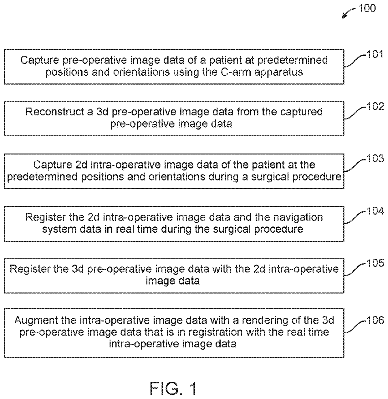
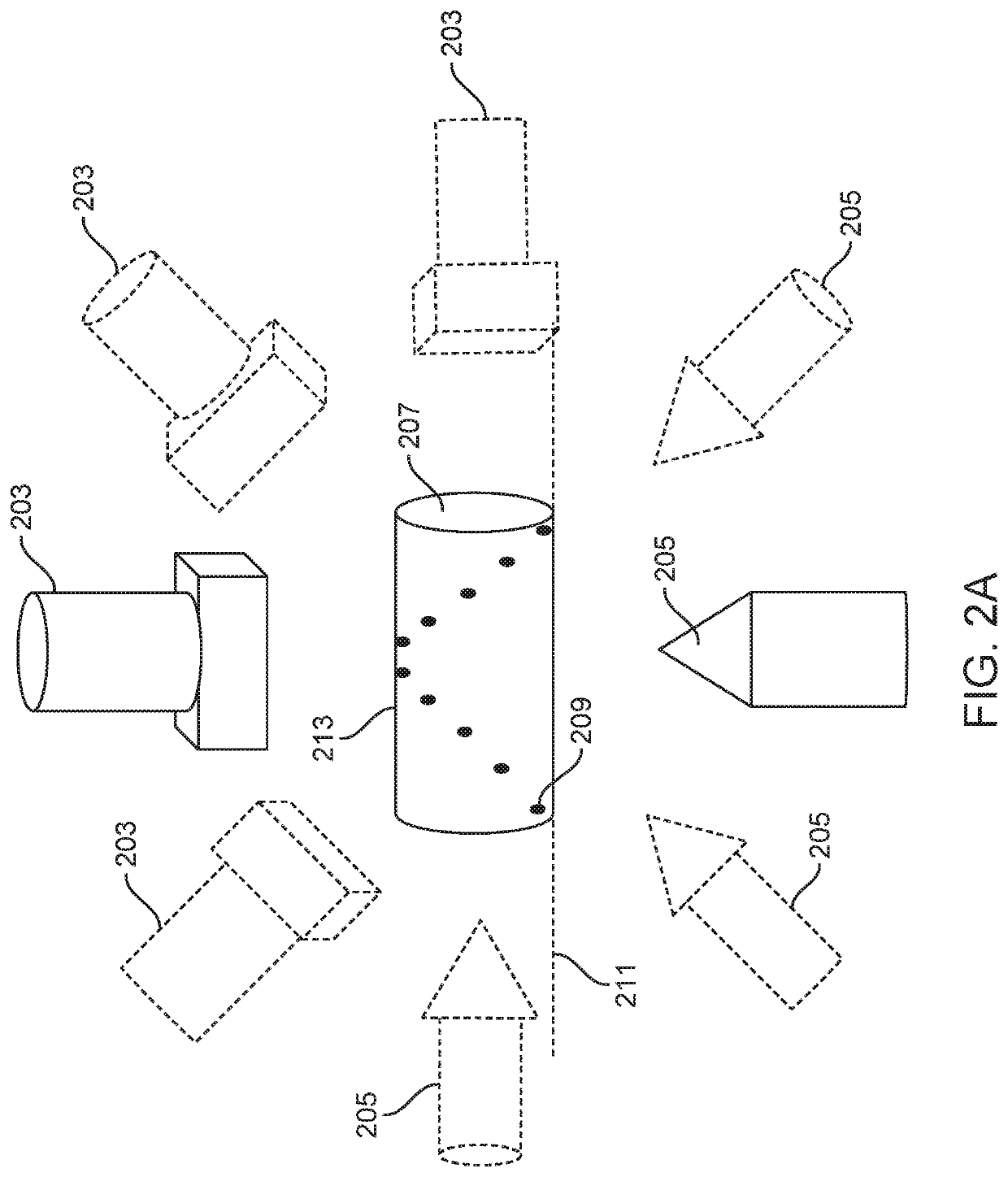
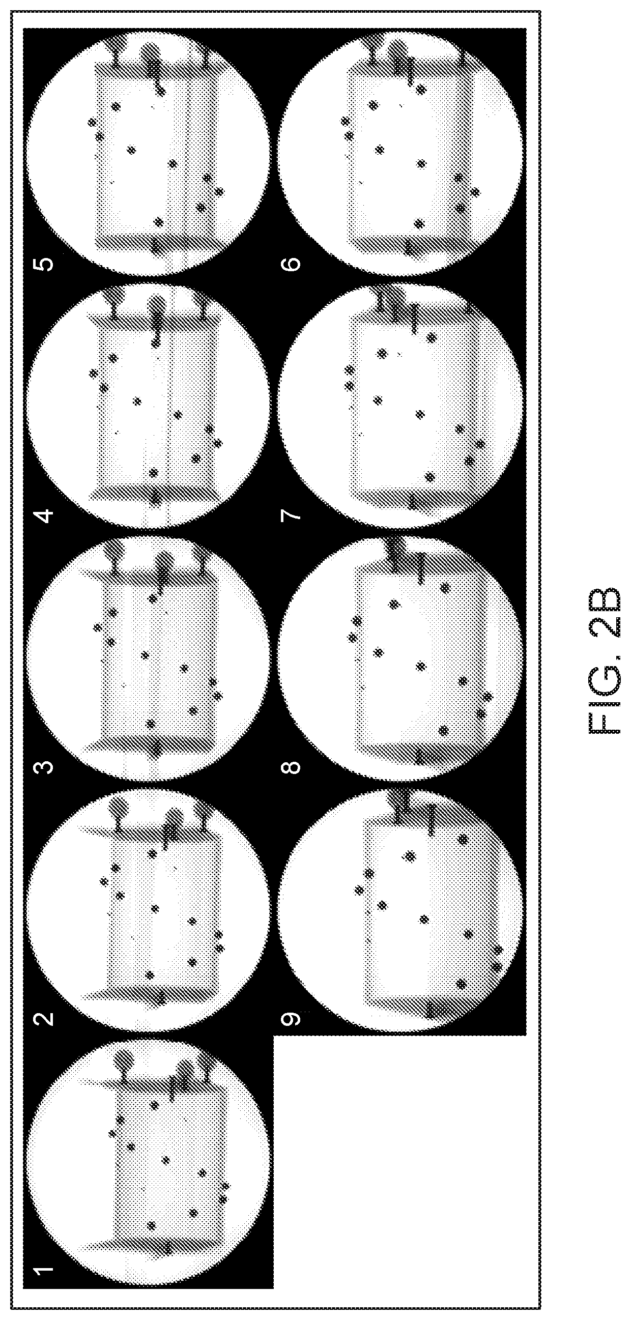
[0007]In various embodiments a method of providing surgical guidance and targeting in robotic surgery systems is disclosed. The robotic surgery systems include an imager that has a source, a detector having a marker and a navigation system that has a tracker. The method includes the steps of capturing by an imaging system pre-operative image data of a patient at predetermined positions and orientations. A 3D pre-operative image data is reconstructed from the captured pre-operative image data using a processing system. 2D intra-operative image data of the patient are captured at the predetermined positions and orientations of the imager during a surgical procedure. The 2D intra-operative image data and the navigation system data in real time during the surgical procedure are registered to track the position of one or more navigated or robotically articulated surgical tools. Further the 2D intra-operative image data are registered with the 3D pre-operative image data. In various embodiments the method augments intra-operative image data with a rendering of the 3D pre-operative image data that is in registration with the real time intra-operative 2D image data.

Problems solved by technology

Registration accuracy is limited by the resolution of each of the different coordinate systems, and the measurement precision of the navigation system.
Further, there are limitations in the acquisition, modality and protocol brought into each coordinate system.
The intra-operative imaging modality such as fluoroscopy permits high resolution cross-sectional or projective views, but reduced to 2D, and mapping to 3D is underdetermined and non-unique.

Method used


Image

  • Robotic surgery systems and surgical guidance methods thereof
  • Robotic surgery systems and surgical guidance methods thereof
  • Robotic surgery systems and surgical guidance methods thereof

Examples


example

Example. 1: Surgical Guidance Method in Robotic Surgery Performed at the Lumbar Spine Region

[0048]The source of the intra-operative mobile C-arm was kept under the table. The position of the C-arm is tracked using an optical marker attached to the detector. The c-arm was calibrated for its intrinsic parameters—specifically the image center, and the focal lengths, assuming the model of a standard pinhole projective camera. The available parameters of the c-arm are the source-detector distance (which is typically in the order of 1000 mm), and the pixel spacing in mm (typically 0.2 to 0.8 mm, image intensifier magnification-dependent).

[0049]Extrinsic calibration of the imager was performed. The objective of extrinsic calibration is to localize the detector image plane in 3D with respect to the surgical site. The extrinsic calibration depict the plane projecting upon which would produce the imaged shot. This plane is given by the composition of the intrinsic parameter matrix and an Eule...


PUM


Abstract

The invention in its various embodiments relates to a method of providing surgical guidance and targeting in robotic surgery systems. The method utilizes data from a navigation system in tandem with 2-dimensional (2D) intra-operative imaging data. 2D intra-operative image data is superimposed with a pre-operative 3-dimensional (3D) image and surgery plans made in the pre-operative image coordinate system. The superimposition augments real-time intraoperative navigation for achieving image guided surgery in robotic surgery systems. Also, a robotic surgery system that incorporates the method of providing surgical guidance and targeting is disclosed. The advantages include minimizing radiation exposure to a patient by avoiding intra-operative volumetric imaging, mobility of tools, imager and robot in and out of the operating space without the need for re-calibration, and relaxing the need for repeating precise imaging positions.

Description

CROSS-REFERENCES TO RELATED APPLICATIONS[0001]This application claims priority to Indian provisional patent application no. 201841048137 entitled Method for utilizing a navigation system in tandem with traditionally used intra-operative imaging in orthopaedic surgery filed on 19 Dec. 2018.FIELD OF THE INVENTION[0002]The disclosure relates generally to image guided surgery and in particular to providing surgical guidance and targeting in robotic surgery systems.DESCRIPTION OF THE RELATED ART[0003]Robotic surgery is an emerging technology that performs minimally invasive surgeries. The step involved in robotic surgery includes obtaining preoperative images of a region to be operated on a patient, transforming the preoperative image data to a coordinate system employed by the robot. Plans are made in the pre-operative image coordinate system and subsequently a medical tool is controlled robotically based on information in the preoperative image. One of the important requirements in rob...

Claims


Application Information

Patent Timeline
Patent Type & Authority Applications(United States)
IPC IPC(8): A61B34/20G06T19/00G06T7/80G06T11/00G06T7/246A61B90/00A61B34/30B25J13/08
CPCA61B34/20A61B2034/2051G06T7/80G06T11/003G06T7/248A61B90/39A61B34/30B25J13/089G06T2211/424G06T2207/10116G06T2207/10132G06T2207/10081G06T2207/10088G06T2207/30004G06T2207/30204A61B2034/2065A61B2090/3762A61B2090/378A61B2090/374A61B2034/2055G06T19/006G06T7/30G06T2207/10121G06T2207/20061A61B2090/376A61B2090/367A61B2090/3966A61B2017/00725A61B2017/00707
Inventor SIVAPRAKASAM, MOHANASANKARRAM, KEERTHILAKSHMANAN, MANOJKUMAR
Owner INDIAN INST OF TECH MADRAS
Why Eureka
Try Eureka