Damper device

a technology of adamant device and a hysteresis torque, which is applied in the direction of mechanical actuated clutches, couplings, slip couplings, etc., can solve the problems of complicated configuration of the hysteresis torque device, and achieve the effect of small hysteresis torque, sufficient hysteresis torque, and simple configuration

Pending Publication Date: 2022-02-24
EXEDY CORP
View PDF0 Cites 0 Cited by
  • Summary
  • Abstract
  • Description
  • Claims
  • Application Information

AI Technical Summary

Benefits of technology

[0007]It is an object of the present invention to enable a damper device, with a simple configuration, to generate a small hysteresis torque in a low torsion angular range and generate a sufficient hysteresis torque in a high torsion angular range, and simultaneously, to effectively attenuate minute vibrations.
[0013]As described above, in the neutral condition, the friction member can be constantly maintained in the neutral position with use of the elastic members basically used in any kind of damper device. Besides, the friction member is not actuated in the low torsion angular range. Contrarily, the friction member is actuated in the high torsion angular range, although not actuated in the minute torsion angular range included in the high torsion angular range. Therefore, the damper device is enabled, with a simple configuration, to obtain a small hysteresis torque in the low torsion angular range and obtain a sufficient hysteresis torque in the high torsion angular range, and simultaneously, to effectively attenuate minute vibrations in traveling.
[0024]In the present damper device, in the neutral condition, the first and second rotors receive both a torsional torque acting to the first side in the rotational direction and a torsional torque acting to the second side in the rotational direction from the first and second elastic members each disposed in the compressed state. Therefore, even in fluctuations in input torque less than or equal to the torsional torque generated by the compressed elastic member, the first and second rotors are not rotated relative to each other. Because of this, it is possible to inhibit collision sound produced between respective members due to torque fluctuations in a predetermined torsion angular range.
[0030]Overall, according to the present invention described above, the damper device is enabled, with a simple configuration, to generate a small hysteresis torque in a low torsion angular range and generate a sufficient hysteresis torque in a high torsion angular range, and simultaneously, to effectively attenuate minute vibrations.

Problems solved by technology

Hence, the damper device is quite complicated in configuration.

Method used


Image

  • Damper device
  • Damper device
  • Damper device

Examples


Embodiment Construction

Entire Configuration

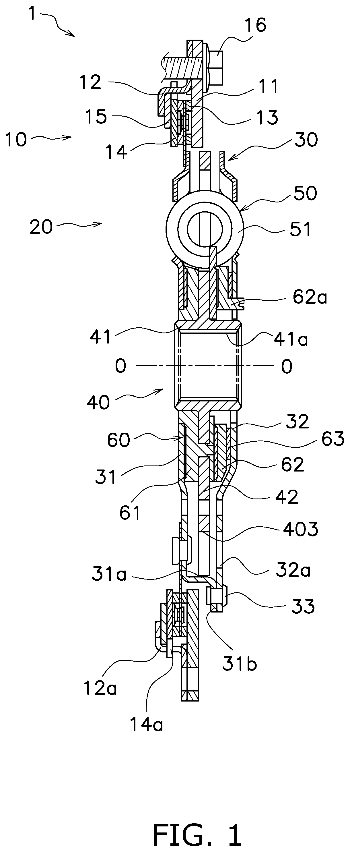
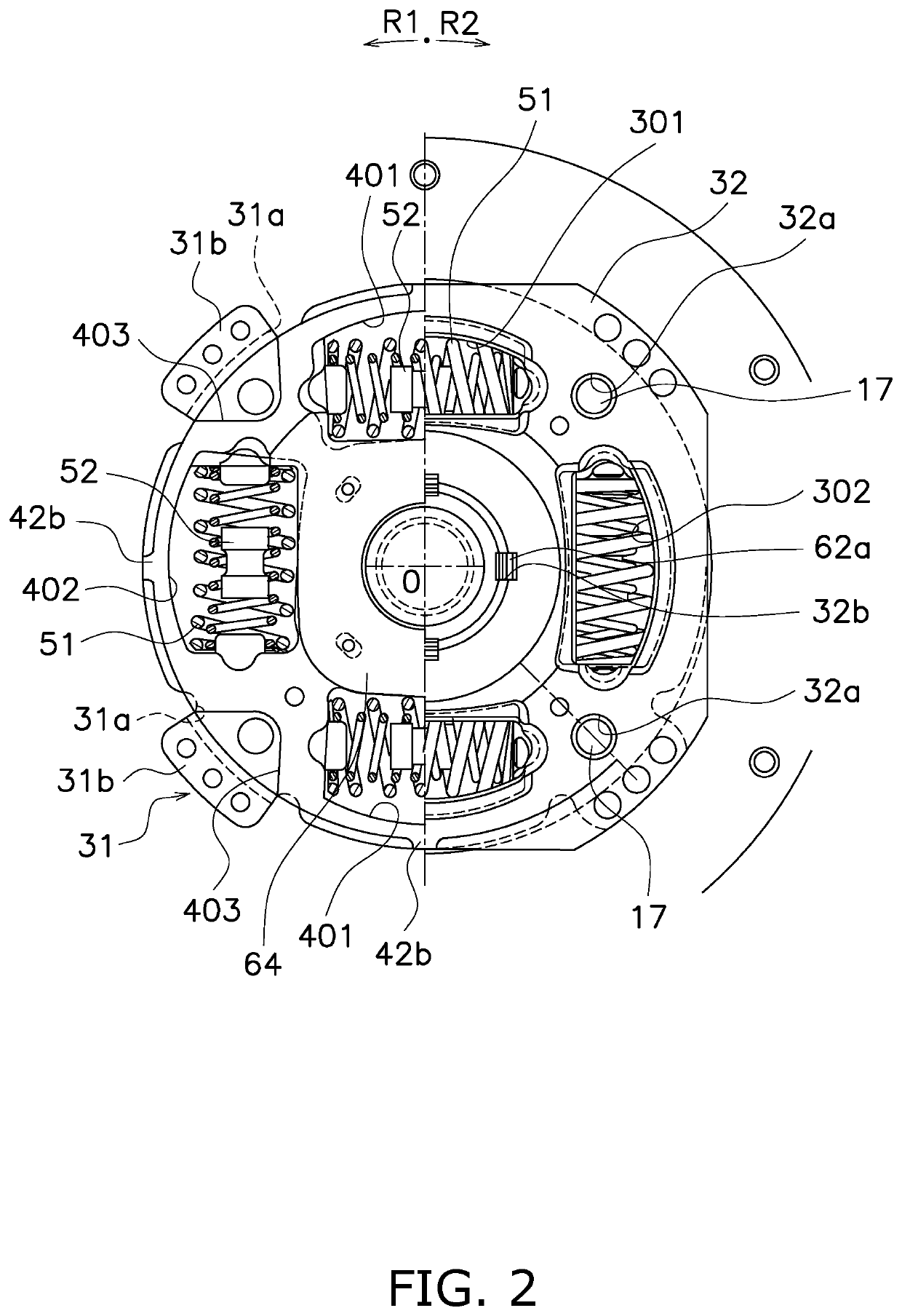
[0050]FIG. 1 is a cross-sectional view of a torque limiter embedded damper device 1 (hereinafter simply referred to as “damper device 1”) according to a preferred embodiment of the present invention. On the other hand, FIG. 2 is a front view of the damper device 1, from part of which some constituent members are detached. In FIG. 1, an engine (not shown in the drawing) is disposed on the left side of the damper device 1, whereas a drive unit (not shown in the drawing), including an electric motor, a transmission, and so forth, is disposed on the right side of the damper device 1.

[0051]It should be noted that in the following explanation, the term “axial direction” refers to an extending direction of a rotational axis O of the damper device 1. On the other hand, the term “circumferential direction” refers to a circumferential direction of an imaginary circle about the rotational axis O, whereas the term “radial direction” refers to a radial direction of the imagin...


PUM


Abstract

A damper device includes a first rotor, a second rotor, an elastic coupling part having first and second elastic members, and a hysteresis generating mechanism. The hysteresis generating mechanism includes a friction member, and generates a hysteresis torque. The friction member does not make frictional contact with the first and second rotors in a first torsion angular range where the torsion is caused between the first and second rotors by a first torsion angle from a neutral condition, makes frictional contact with the first or second rotor in a second torsion angular range exceeding the first torsion angle so as to generate the hysteresis torque, and does not make frictional contact with the first and second rotors in a predetermined torsion angular range within the second torsion angular range. In the neutral condition, the friction member is set in a neutral position by actuation of the elastic coupling part.

Description

CROSS-REFERENCE TO RELATED APPLICATIONS[0001]This application claims priority to Japanese Patent Application No. 2020-139616, filed Aug. 20, 2020. The entire contents of that application are incorporated by reference herein in their entirety.TECHNICAL FIELD[0002]The present invention relates to a damper device.BACKGROUND ART[0003]In general, noises and vibrations of vehicles include noises in idling, noises in traveling, and tip-in / tip-out (low frequency vibrations). Damper devices are provided for inhibiting the noises and vibrations described above.[0004]In torsional characteristics of a damper device, a low torsion angular range relates to noises in idling, and a low torsional stiffness is preferable in the low torsion angular range. On the other hand, to countermeasure tip-in / tip-out, the torsional characteristics are required to have the highest possible stiffness in a high torsion angular range. Moreover, when minute vibrations attributed to e.g., variation in engine combustio...

Claims


Application Information

Patent Timeline
Patent Type & Authority Applications(United States)
IPC IPC(8): F16F15/139F16D3/12F16D13/64F16F15/134F16F15/14
CPCF16F15/1392F16D3/12F16D2300/22F16F15/134F16F15/145F16D13/64F16F15/12373F16F15/13492F16D43/26F16D7/025
Inventor UEHARA, HIROSHIAOKI, MASAHIKO
Owner EXEDY CORP
Why Eureka
Try Eureka