Gas inhalation device with constant concentration of gas entering respiratory tract and without respiratory resistance

a gas inhalation device and constant concentration technology, applied in the field of medical devices, can solve the problems of air retention and discomfort, decrease in the partial pressure of cosub>2 /sub>in the blood, anesthesia in the respiratory center, etc., and achieve the effect of avoiding facial pressure and discomfort, and reducing the retention of expiratory gas

Pending Publication Date: 2022-03-03
LUO YUANMING
View PDF0 Cites 0 Cited by
  • Summary
  • Abstract
  • Description
  • Claims
  • Application Information

AI Technical Summary

Benefits of technology

[0018]After the patient wears the mask and the adapter tube at the proximal end of the mask is connected to a gas mixer or gas source with a constant output flow rate (for example, 60 L/min) through the connector and the gas delivery pipe, the gas will be evenly delivered to enter the mask cavity around the proximal end of the mask and flows out from the distal end of the mask. Because a plurality of large orifices or one huge orifice are provided at the distal end of the mask with a large aperture and with almost no resistance and the pressure in the mask being always zero, all the gas in the mask is discharged through the large or huge orifices at the distal end of the mask. Even if the connection between the mask and the face is not completely tight, since the gas flow into and out of the large orifices or the huge orifice at the distal end is far less resistant than the connection between the mask and the face, all gas in the mask will still be discharged from the distal end of the mask. Because the gas source or the gas mixer is connected to the catheter surrounding the proximal end of the mask and with a plurality of small orifices through the gas delivery pipe and the adapter tube at a constant flow rate, and the small orifices on the catheter communicate with the inner cavity of the mask, the gas is continuously delivered from the proximal end of the mask to the mask cavity and discharged from the distal end, and at the same time, the expiratory gas is expelled from the distal end of the mask, so that the gas staying at the proximal end of the mask before inhalation is essentially the gas from th

Problems solved by technology

CO2 is a stimulant driven by the respiratory center, but too high CO2 concentration can cause anesthesia in the respiratory center.
The main cause of heart failure combined with central apnea is the decrease in the partial pressure of CO2 in the blood.
When the concentration of the inhaled CO2 is too low, it will not have a therapeutic effect, and if it is too high, it will cause arousal.
Since the apertures of the small orifices on both sides of the mask cannot be too large to prevent excessive air from entering the mask during inhalation to decrease the concentration of inhaled gas.
If the apertures of the small orifices on both sides of the mask are small, it will affect the discharge of expiratory gas, causing air retention and discomfort.
Since patients with heart failure and central sleep apnea are often accompanied by insomnia, the additional breathing resistance will further

Method used


Image

  • Gas inhalation device with constant concentration of gas entering respiratory tract and without respiratory resistance
  • Gas inhalation device with constant concentration of gas entering respiratory tract and without respiratory resistance
  • Gas inhalation device with constant concentration of gas entering respiratory tract and without respiratory resistance

Examples


Embodiment Construction

[0029]The present invention will be further described below in conjunction with the drawings and embodiments.

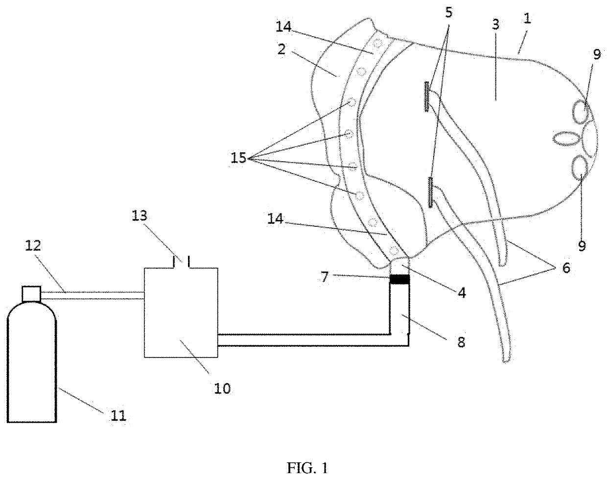
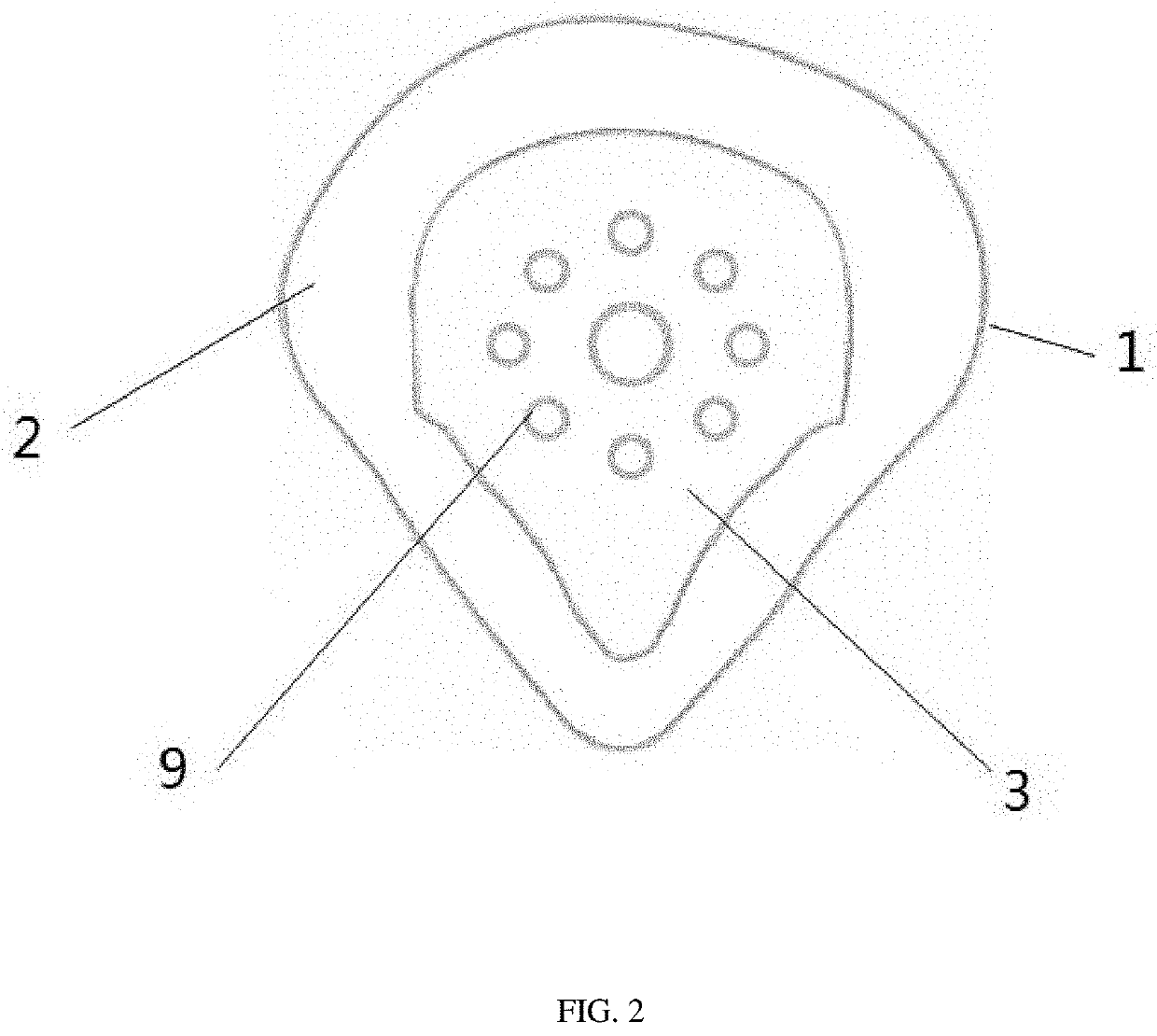
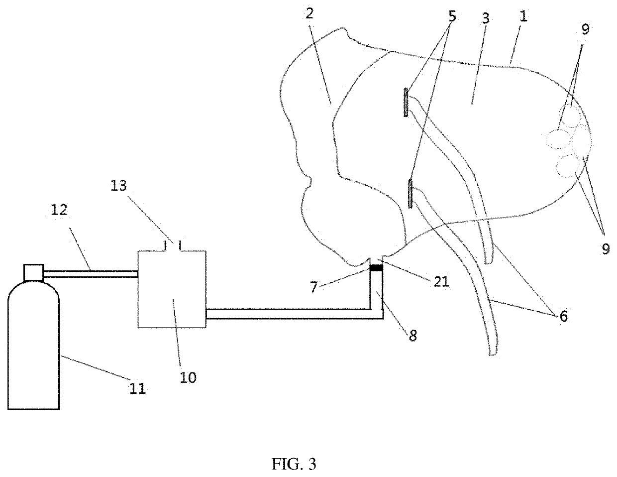
[0030]FIG. 1 shows the appearance of a gas inhalation device. It includes a mask 1, a gas source 11, a gas mixer 10 and connecting pipes 8 and 12. The mask 1 includes a soft cushion 2 connected to the face and a mask body 3. The mask body 3 is capable of holding 50-1000 ml of gas. One or two headband fixing bayonets 5 are provided on both sides of the mask's outer layer and connected to a headband 6. An adapter tube 4 is provided at the cushion 2 at the proximal end of the mask. One end of the adapter tube 4 is connected to a catheter 14 surrounding the mask. A plurality of small orifices 15 communicating with the mask cavity are provided on the catheter. The gas delivery pipe 8 is connected to one end of the adapter tube 4 by a connector 7. The gas source 11 is a high-pressure gas, which is connected to the gas mixer 10 through the connecting pipe 12. The concentration of th...


PUM


Abstract

The present invention provides a gas inhalation device with a constant concentration of gas entering the respiratory tract and without respiratory resistance, including: a mask, a gas source and a gas mixer, wherein the mask is a container that is capable of holding 50-1000 ml of gas, a proximal end of the mask is a soft cushion for fitting the face and surrounded by a catheter, the catheter is provided with a plurality of small orifices communicating with an inner cavity of the mask, one end of the catheter is connected to one end of an adapter tube, the other end of the adapter tube is connected to a gas delivery pipe, the gas delivery pipe is a catheter connecting the adapter tube and the gas source or the gas mixer; a distal end of the mask is provided with a huge orifice or a plurality of large orifices to ensure unobstructed gas in and out, with almost no airflow resistance, and an internal pressure of the mask cavity is always zero; one or two headband interfaces are provided on both sides of the mask's outer layer for connecting a headband fixing the mask to ensure that the mask is stably fixed on the face.

Description

TECHNICAL FIELD[0001]The present invention relates to a medical treatment device, and in particular to a gas inhalation device with a constant concentration of gas entering the respiratory tract and without respiratory resistance.BACKGROUND[0002]The implementation of gas therapy, such as oxygen therapy in respiratory failure, and CO2 treatment of central sleep apnea, require a gas inhalation device, especially a gas inhalation device with a constant concentration of inhaled gas. CO2 is a stimulant driven by the respiratory center, but too high CO2 concentration can cause anesthesia in the respiratory center. It is very important to control the amount of CO2 inhaled. The main cause of heart failure combined with central apnea is the decrease in the partial pressure of CO2 in the blood. Inhalation of CO2 can eliminate central sleep apnea in patients with heart failure. However, the concentration of CO2 during central sleep apnea is slightly different from the blood CO2 during normal b...

Claims


Application Information

Patent Timeline
IPC IPC(8): A61M16/06A61M16/08A61M16/12A61M16/10
CPCA61M16/0611A61M16/0875A61M16/12A61M16/0633A61M2202/0208A61M2202/0225A61M2202/02A61M2202/025A61M16/1005A61M16/06A61M16/0003A61M2205/33A61M2202/0007A61M16/0683A61M16/125A61M2202/0085
Inventor LUO, YUANMINGLUO, YINGMEIZHONG, NANSHAN
Owner LUO YUANMING
Why Eureka
Try Eureka