Two-stroke internal combustion engine

a two-stroke, internal combustion engine technology, applied in combustion engines, valve arrangements, machines/engines, etc., can solve the problems of increased consumption, decreased efficiency, and dangerous health effects of polluting gases, and achieves reduced polluting emissions, sufficient time available, and the effect of reducing pollution

Active Publication Date: 2022-03-03
EMAK
View PDF0 Cites 0 Cited by
  • Summary
  • Abstract
  • Description
  • Claims
  • Application Information

AI Technical Summary

Benefits of technology

[0028]Thanks to this solution it is possible to reduce consumption and improve the environmental impact of the engine, even without significantly affecting the performance thereof. This is because through the partition, it is prevented that, in the first opening step of the outlet mouth of the transfer duct, the pressure obtained in the cylinder downstream of the first spontaneous exhaust step may recall fresh mixture through the transfer duct and because the obstruction of the inlet port of the transfer duct in a step in which the piston is reducing the size of the pumping chamber allows generating an overpressure in the pumping chamber, greater than in a two-stroke engine not provided with the movable partition, which allows the mixture to be brought into the pumping chamber in a short time and with a greater pressure than an engine not provided with the movable partition.

Problems solved by technology

A known problem is that during the washing step, due to the intrinsic conformation of the two-stroke engine whereby there is a complete overlap between the period of time in which the outlet mouth of the transfer duct is placed in communication with the combustion chamber and the period of time in which the inlet mouth of the exhaust duct is placed in communication with the expansion chamber, part of the fresh charge pumped by the cylinder into the expansion chamber through the transfer duct is directly ejected through the exhaust duct.
Consequently during this step, the two-stroke engine gives the environment a high quantity of gasoline and oil, which are pollutants dangerous for health.
Moreover, this loss of fresh mixture in the exhaust duct causes a decrease in efficiency, therefore an increase in consumption, with respect to an ideal cycle in which all the fresh mixture remains in the cylinder following the washing step.
However, this solution is penalizing from the point of view of efficiency, understood as the ratio between the energy generated and the mechanical losses, because it causes an increase in the load losses suffered by the fresh mixture in passing through the transfer duct and consequently an increase in the energy absorbed by the piston to pump the fresh mixture from the pumping chamber to the combustion chamber through the transfer ducts.

Method used


Image

  • Two-stroke internal combustion engine
  • Two-stroke internal combustion engine
  • Two-stroke internal combustion engine

Examples


Embodiment Construction

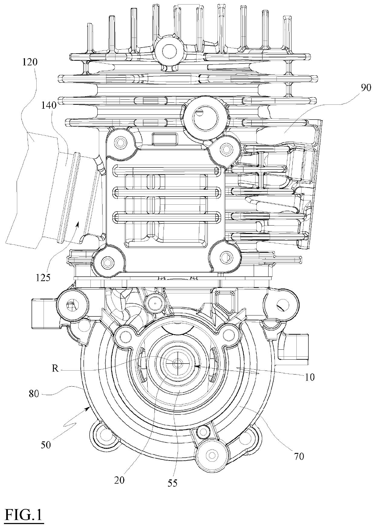
[0053]With particular reference to such figures, reference numeral 1 globally indicates a two-stroke internal combustion engine, which can be fed by a gaseous mixture composed of air, fuel and lubricating fluid.

[0054]To promote compactness and clarity of reading, the two-stroke internal combustion engine 1 will be referred to as engine 1 hereinafter.

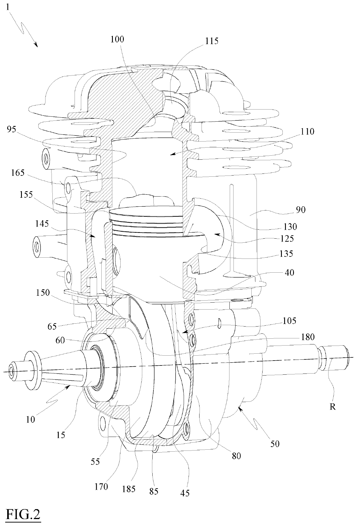
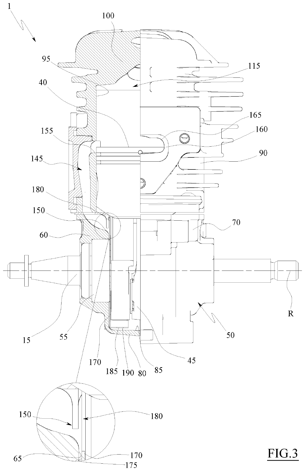
[0055]The engine 1 comprises a crank shaft 10 adapted to rotate with respect to a rotation axis R and through which the driving force generated by the engine itself is removed.

[0056]It should be noted that crank shaft means a shaft integrating a crank, which has an end portion crossed by the shaft rotation axis and an opposed end portion distal from said rotation axis.

[0057]The crank shaft 10 may comprise a first cylindrical section 15 coaxial to the rotation axis R, a second cylindrical section 20 opposed to the first cylindrical section 15 and coaxial to the rotation axis R, and a crank 25 which connects the first cylindrical section 1...


PUM


Abstract

A two-stroke internal combustion engine includes:—a base;—a head, fixed to the base, and having a cylindrical cavity;—a piston slidable in the cylindrical cavity, to define a combustion chamber and a pumping chamber, and movable in the cylindrical cavity between a bottom and a top dead center;—a transfer duct having an inlet mouth in fluid communication with the pumping chamber, and an outlet mouth in fluid communication with the combustion chamber;—an exhaust duct having an inlet mouth in fluid communication with the combustion chamber,—a crank shaft partially housed in the pumping chamber;—a connecting rod connecting the piston to the crank shaft;—a movable partition housed inside the pumping chamber operatively connected to the crank shaft to occlude the transfer duct inlet mouth and to put in fluid communication the transfer duct inlet mouth with the pumping chamber.

Description

TECHNICAL FIELD[0001]The present invention relates in general to a two-stroke internal combustion engine. More particularly, the present invention relates to a two-stroke internal combustion engine of medium-small size, adapted to be installed on portable working tools, such as gardening tools such as brush cutters, lawn mowers, chain saws and the like.PRIOR ART[0002]Two-stroke internal combustion engines generally comprise a base in which a crank chamber is obtained, i.e. a chamber adapted to contain the crank shaft of the engine, and a head fixed above the base.[0003]Inside the head of the engine there is obtained at least a straight cylinder that in the lower part flows into the crank chamber.[0004]Inside the cylinder, a piston is free to slide, which separates a combustion chamber, defined inside the cylinder, from a pumping chamber, defined inside the crank chamber.[0005]The piston is connected to the crank shaft through a connecting rod and is movable between a bottom dead cen...

Claims


Application Information

Patent Timeline
Patent Type & Authority Applications(United States)
IPC IPC(8): F02B25/16F02B75/02
CPCF02B25/16F02B2075/025F02B75/02F01L7/12F02B25/24F02B33/04F02B25/14
Inventor BERTANI, ANDREA
Owner EMAK
Why Eureka
Try Eureka