Method for varnishing plated parts

a technology of chromium plated parts and varnishing, which is applied in the direction of electrolytic coatings, electrolytic inorganic material coatings, liquid/solution decomposition chemical coatings, etc. it can solve the problems of difficult industrial application, difficult to achieve the effect of reducing the risk of deterioration of non-metal substrates, and relatively expensive methods

Inactive Publication Date: 2016-05-05
DOURDIN
View PDF4 Cites 0 Cited by
  • Summary
  • Abstract
  • Description
  • Claims
  • Application Information

AI Technical Summary

Benefits of technology

[0024]It will be understood that the drying step with ultraviolet radiation uses an operating temperature lower than more conventional thermal drying temperatures for which the temperature is above 120° C. The non-metal substrate is therefore subjected to a lower temperature range thereby reducing the risk of degradation of said non-metal substrate.
[0025]Furthermore, in another embodiment, the drying step of the varnish layer is conducted using a device which pulses hot air onto the varnish layer at temperatures lower than 120° C. Therefore in the same manner as for ultraviolet drying, the use of hot air at temperatures below 120° C. reduces the risk of deteriorating the non-metal substrate.
[0026]Preferably, the varnish layer is transparent or coloured. Therefore by means of the invention, a transparent varnish layer allows the exposing of the natural colour of the reinforcement layer or of the nickel layer underlying the varnish layer. Also, the varnish layer may be tinted to obtain a coloured plated part. The part therefore adapts to the aesthetic environment in which said part is to be integrated.

Problems solved by technology

However, these methods have the disadvantage of being relatively costly due to the energy required and the conditions under which they must be performed.
Additionally, they are difficult to apply at industrial level.
However, chromium and in particular hexavalent chromium used for plating has the drawback of being toxic for the environment.
The cost involved for the production of plated parts is therefore high.
Trivalent chromium is also a toxic chemical product.
Trivalent chromium raises the same problems as hexavalent chromium.
A further disadvantage of the use of chromium is that the production thereof gives rise to a high rejection rate of produced parts.
This high rejection rate therefore increases production costs of the parts.

Method used


Image

  • Method for varnishing plated parts
  • Method for varnishing plated parts

Examples


Embodiment Construction

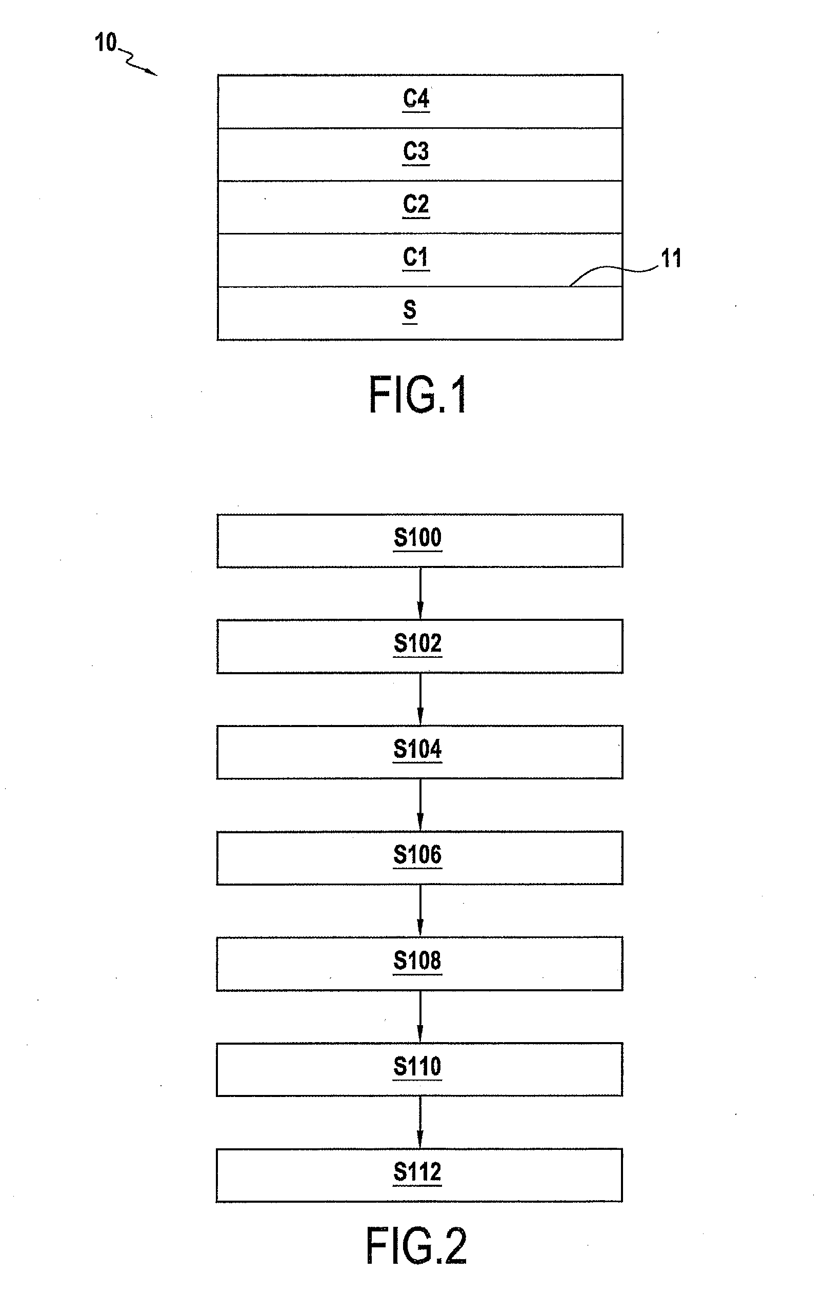
[0055]FIG. 1 schematically illustrates a plated part 10 free of chromium conforming to the invention. This part comprises a non-metal substrate S on which layers C1 to C4 will be deposited. The non-metal substrate S has a surface 11.

[0056]In this example, the non-metal substrate S is a part in plastic material. In this example, the substrate consists of ABS (Acrylonitrile Butadiene Styrene) which has good mechanical strength and corrosion resistance. In one variant, a copolymer is used comprising acrylonitrile butadiene styrene and a polycarbonate.

[0057]In addition, in another example, the metal substrate can composed of a polyamide.

[0058]In another variant, the non-metal substrate S comprises polypropylene.

[0059]In FIG. 2, a first step S100 is the step at which the substrate S in plastic material receives chemical treatment on its surface 11 to obtain roughness of said surface 11.

[0060]In this example, the chemical attack of the surface 11 of a part containing an acrylonitrile buta...


PUM

PropertyMeasurementUnit
temperatureaaaaaaaaaa
temperaturesaaaaaaaaaa

Abstract

A method is provided for plating a non-metal substrate (S), allowing a plated part to be obtained. The method includes steps of: (a) providing a non-metal substrate (S) having a surface (11); (b) forming a bonding layer (C1) on the surface (11); (c) forming at least one reinforcement layer (C2) on the bonding layer (C1); (d) forming a varnish layer (C4) above the reinforcement layer (C2); and performing a drying step to dry the varnish layer, wherein the varnish layer is exposed to ultraviolet radiation.

Description

BACKGROUND OF THE INVENTION[0001]The present invention relates to the field of methods for plating parts and in particular non-metal substrates. Different manners are known to plate a non-metal substrate.[0002]In particular, dry processes are known using plasma or flame spray. Vacuum plating methods are also known such as PVD for example. However, these methods have the disadvantage of being relatively costly due to the energy required and the conditions under which they must be performed. Additionally, they are difficult to apply at industrial level.[0003]Plating methods are also known via electrolytic route whereby a layer of chromium is deposited.[0004]One advantage of this type of method is the obtaining of plated parts having a metal appearance. These parts are particularly used in the motor vehicle industry.[0005]However, chromium and in particular hexavalent chromium used for plating has the drawback of being toxic for the environment. Hexavalent chromium requires closed circ...

Claims


Application Information

Patent Timeline
Patent Type & Authority Applications(United States)
IPC IPC(8): C25D9/04C25D5/50C25D7/00
CPCC25D9/04C25D5/50C25D7/00C25D5/14C25D13/22C23C18/1653C25D5/12C23C18/2086C23C18/24C23C18/285C23C18/30C25D5/625C25D5/627C25D5/623
Inventor DOURDIN, HUGUESDOURDIN, ERIK
Owner DOURDIN
Why Eureka
Try Eureka