Green retaining wall utilizing helical piers

a technology of helical piers and retaining walls, which is applied in the direction of mining structures, artificial islands, excavations, etc., can solve the problems of small strength, short service life, and inability of walls to withstand movement of soil, and achieves reduced cost, substantial load-bearing capacity, and reduced assembly time and environmental impact

Inactive Publication Date: 2010-03-16
RABICHEV VAL +1
View PDF21 Cites 1 Cited by
  • Summary
  • Abstract
  • Description
  • Claims
  • Application Information

AI Technical Summary

Benefits of technology

[0008]The present invention provides a system and a method for a retaining wall which minimize cost, assembly time and environmental impact while providing substantial load-bearing capacity.
[0009]An important feature of the present invention is that it permits the ready strengthening of existing or newly built retaining walls that, by themselves, have insufficient strength and durability to retain an embankment, for example, and prevent an eventual deterioration and collapse of the wall.
[0012]Both types of the specifically described retaining walls, as well as others, are desirable because they are environmentally friendly, require little disturbance of the soil along the embankment, introduce a minimal amount of foreign materials to the site, and permit plantings into the wall through holes provided for this purpose to render the wall attractive and more green.
[0013]This is accomplished in accordance with the present invention by providing a harness over the exterior of the wall that has upright, typically vertically oriented or slightly inclined, helical piers, helical tie-back piers which extend at an angle to the horizontal through the embankment into the soil behind it, connectors which are secured to the helical piers and tie-backs, and generally horizontally oriented waler rods secured to the connectors and arranged so that they contact and provide support for the upright lagging or the Geotextile fabric, for example, of the retaining wall. The connector itself is securely tightened to the helical pier and the inclined tie-back rods to provide vertical and horizontal support for the retaining wall. The resulting harness leaves most of the attractive retaining wall, whether it be a wooden wall, a Geotextile fabric wall, or a wall made of another material. The wall remains visible and is only very slightly obstructed by the vertical pier rods, the waler rods and the connectors between them. As a result, access to the soil behind the retaining wall can be provided through relatively small openings where vegetation, brush and the like can be planted which both enhance the aesthetic appearance of the wall while the root system of the vegetation strengthens and solidifies the soil behind the wall.
[0014]Thus, the system of the present invention has helical piers driven into the soil that provide anchoring resistance against the load exerted on the retaining wall by the retained soil. Multiple levels of the load-bearing structure can be built on top of each other depending on the height of the soil to be retained. Loads from the retained soil are transferred to the extension bars and waler rods through wood lagging, wood panels, different types of plates, or some other intermediary. A mesh support for the soil can be provided in addition to the load-bearing structure. Trees, bushes or other plants can be planted through the mesh in the retained soil to improve the environmental impact of the invention.
[0016]In one aspect, the interlocking hardware has slotted holes for the horizontal waler rods to provide for better flexibility and higher load bearing.

Problems solved by technology

Such a wall by itself has little ability to withstand movement of the soil and will collapse after a relatively short service life.
The Geotextile fabric has excellent soil-retaining qualities but little strength.
Thus, like in the case of a retaining wall made of wooden boards and lagging, the “woven” Geotextile fabric / soil layers will move and fail.

Method used


Image

  • Green retaining wall utilizing helical piers
  • Green retaining wall utilizing helical piers
  • Green retaining wall utilizing helical piers

Examples


Embodiment Construction

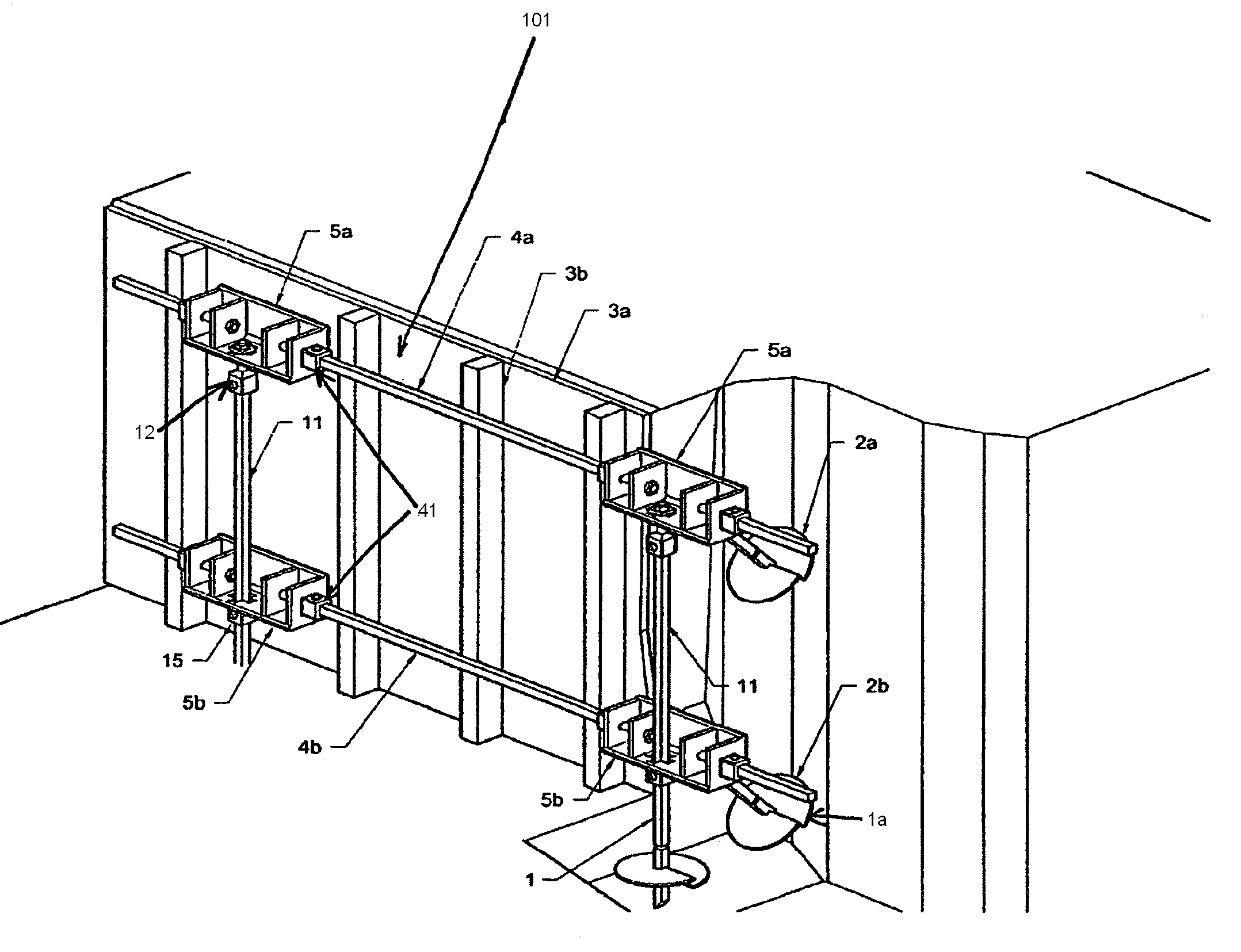
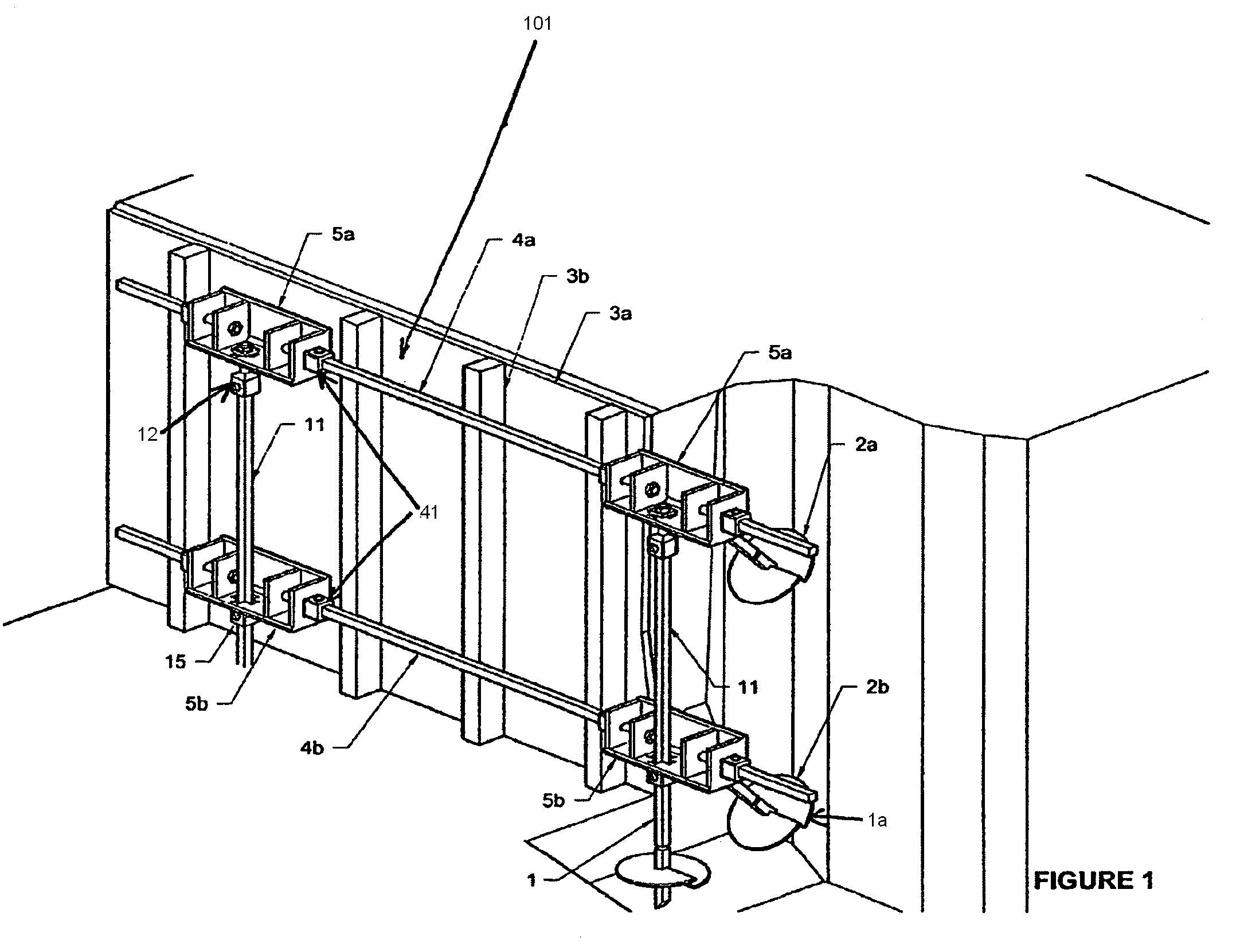
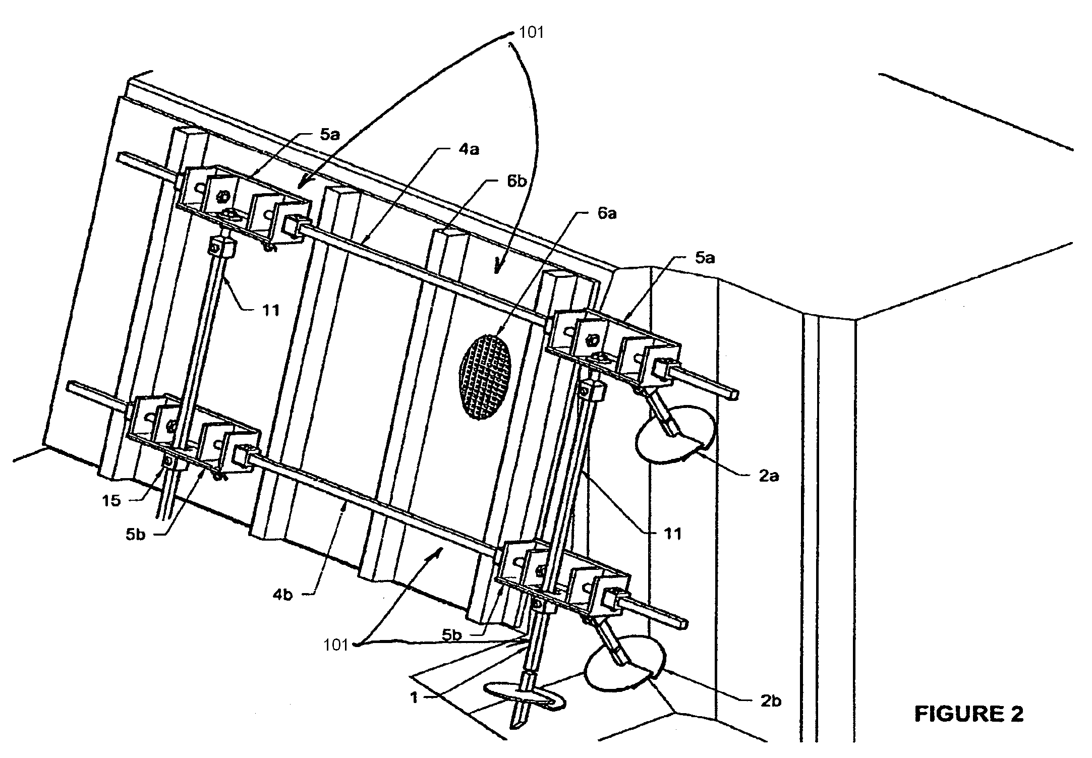
[0024]The embodiments of the present invention are directed toward systems and methods for a soil retaining wall which minimize cost, assembly time and environmental impact while providing a substantial load-bearing capacity. The details of an exemplary embodiment of the present invention are explained with reference to FIGS. 1-4. The exemplary embodiment is described with reference to a two-level system, but it will be clear to a person skilled in the art that the described system and method can be used for any number of levels, depending on the height of the soil to be retained. Also, vertical wood lagging is illustrated as the load transmitter between the soil and the described embodiment, but a person skilled in the art would readily know of other suitable materials in other shapes that may be used.

[0025]FIG. 1 shows a wall retaining system or harness 101 that includes a vertical helical pier lead section 1, which is rotated into the ground to a required depth. Helical piers gen...


PUM


Abstract

The present invention provides a system and a method for a retaining wall which minimizes cost, assembly time and environmental impact while providing substantial load-bearing capacity. The system includes: a plurality of vertical helical piers driven into the ground, tie-back helical piers driven at a non-vertical angle into the ground, substantially horizontal waler rods, and substantially vertical extensions, which are interconnected through interlocking connectors. Multiple levels of the load-bearing structure can be built on top of each other depending on the height of the soil to be retained. Loads from the retained soil may be transferred to the extension bars and waler rods through wood lagging, wood planks, different types of plates, or some other intermediary. A mesh support for the soil can be provided in addition to the load-bearing structure. Trees, bushes or other plants can be planted through the mesh in the retained soil to improve the environmental impact of the invention.

Description

CROSS-REFERENCES TO RELATED APPLICATIONS[0001]This application claims the benefit under 35 U.S.C. §119(e) of U.S. Provisional Patent Application No. 61 / 065,196, filed Feb. 7, 2008, the full disclosure of which is incorporated herein by reference.BACKGROUND OF THE INVENTION[0002]The present invention relates to systems and methods for retaining walls that support vertical or inclined excavation cuts, embankments and the like. In particular, the present invention introduces an environmentally friendly, modular and inexpensive way of structurally supporting soil through helical piers driven into the ground, horizontal waler rods, vertical extensions and interlocking connectors. The resulting structure can withstand high structural loads, while creating a minimal environmental impact.[0003]Retaining walls in civil engineering serve to prevent erosion or a collapse of excavation cuts and soil embankments. They must withstand significant structural loads, while minimizing the cost, the ti...

Claims


Application Information

Patent Timeline
Patent Type & Authority Patents(United States)
IPC IPC(8): E02D29/02
CPCE02D5/74E02D5/801E02D29/02
Inventor RABICHEV, VAL A.BAUMSTEIGER, CHRIS
Owner RABICHEV VAL
Why Eureka
Try Eureka