
Autofocus optical arrangements and assemblies including voice coil motors

a technology of voice coil motors and optical arrangements, which is applied in the direction of mountings, instruments, sensing record carriers, etc., can solve the problems of slow and/or wearout, cost prohibitive solutions, and inability to meet the requirements of mechanical tolerance, so as to reduce mechanical tolerance sensitivity and prevent damage to the focus lens

Pending Publication Date: 2022-03-03
ZEBRA TECH CORP
View PDF2 Cites 3 Cited by
  • Summary
  • Abstract
  • Description
  • Claims
  • Application Information

AI Technical Summary

Benefits of technology

The patent is about improving the design of small barcode readers and cameras by using special optical arrangements. These arrangements use voice coil motors to adjust focus and have a low cost, durable, long life, and compact variable focus lens with increased focal length and extended focusing range. The optical power enhancement provided by the arrangements can be used for machine vision applications and barcode reading. The arrangements are designed to prevent damage to the focus lens and manage imaging lens aberrations. Overall, the patent provides a solution for creating affordable and efficient barcode readers and cameras with increased focal length and range.

Problems solved by technology

Some such solutions may be cost prohibitive, large, slow and / or may wear out with time.
Some such solutions may be cost prohibitive, and / or may have optical characteristics that vary with time and / or temperature.
However, it can be difficult to combine increased focal length, extended focusing range in a compact lens design.
Further, conventional voice coil motors often have load bearing limits of less than 100 milligrams.
At the same time, while step motors have larger strokes and larger weight bearing capabilities they are quite large, slow, expensive, and may wear out over time.

Method used


Image

  • Autofocus optical arrangements and assemblies including voice coil motors
  • Autofocus optical arrangements and assemblies including voice coil motors
  • Autofocus optical arrangements and assemblies including voice coil motors

Examples


Embodiment Construction

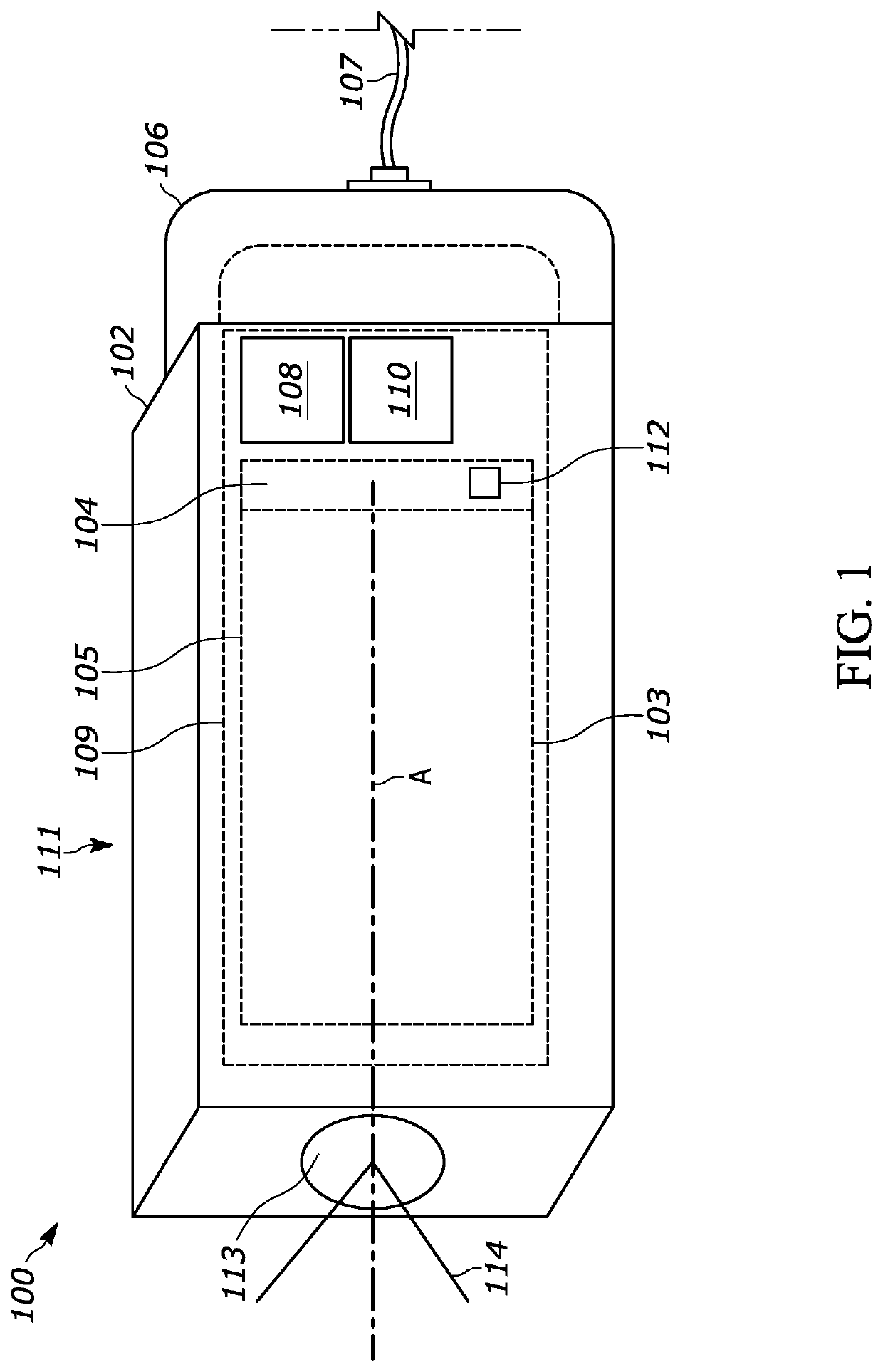
[0025]For ease of reference, aspects of this disclosure will be described in connection with lenses and lens elements. However, one of ordinary skill in the art will readily recognize that any other type(s) of optical elements may, additionally and / or alternatively, be used to implement optical assemblies.

[0026]Portable, high-performance optical imaging systems for machine vision, barcode reading, etc. applications employ small image sensors to maintain small form factors. For example a typical image sensor has an image sensor rectangular area of around 3 by 3 millimeters with sensor pixels areas of approximately 3 by 3 micrometers, i.e., microns. In some embodiments, the optical assembly 105 is configured to capture images with a modulation transfer function of 40% at 160 line pairs per millimeter. Some high-performance compact imaging systems require a large focal length (e.g., a telephoto optical arrangement with greater than range of focal lengths of 5 to 50 millimeters) and sma...


PUM


Abstract

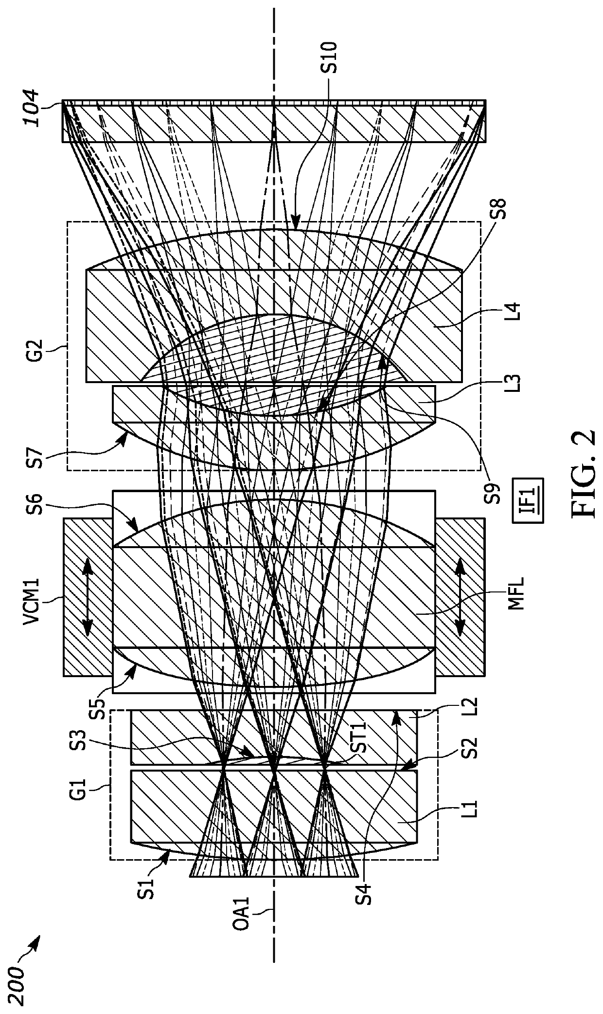
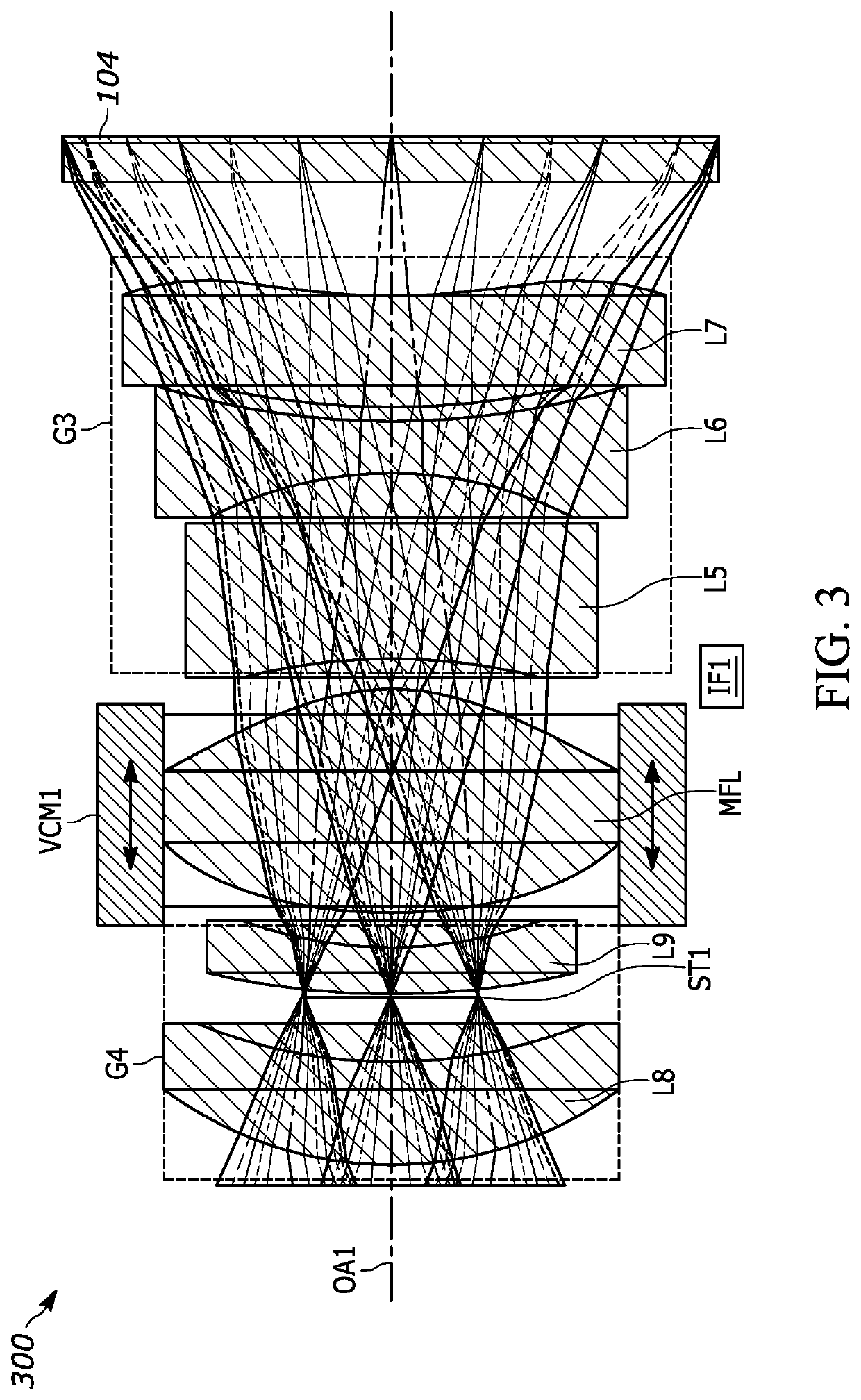
Autofocus (AF) optical arrangements and assemblies including a voice coil motor (VCM) are disclosed. An example optical assembly for a focusing lens includes: a front lens group disposed along an optical axis configured to receive light from the object of interest and configured to correct for aberrations of a first image projected by the front lens group; an aperture disposed along an optical axis configured to receive light from the front lens group therethrough along the optical axis; a moveable focus lens to receive light through the aperture; a VCM configured to move the focus lens to focus the optical assembly; and a back lens group disposed along the optical axis configured to receive light from the focus lens and further configured to correct for field curvature.

Description

BACKGROUND[0001]Imaging devices generally capture images within a given field of view (FOV). It is often required that machine vision devices, barcode readers, etc. capture images with resolution sufficient at suitable distances for effective decoding of indicia captured in an image for use in, e.g., machine vision applications, barcode reading, etc.SUMMARY[0002]The demand for machine vision applications, barcode reading, etc. is increasing, which increasingly requires the use of smaller sensors, and smaller, less expensive and lighter optical arrangements for such devices. However, such devices still need to be capable of generating images with sufficient resolution, at larger focal lengths, over larger focus ranges, across wider temperature ranges, etc. Some conventional autofocus (AF) optical assemblies use mechanical movement of lenses (e.g., using a step motor) to adjust the focus. Some such solutions may be cost prohibitive, large, slow and / or may wear out with time. Alternati...

Claims


Application Information

Patent Timeline
Patent Type & Authority Applications(United States)
IPC IPC(8): G02B7/09G02B13/18G02B9/12
CPCG02B7/09G02B9/12G02B13/18G02B7/28G06K7/10831G06K7/10821G02B15/143
Inventor VINOGRADOV, IGORSHI, DAVID T.TAN, CHINHGUREVICH, VLADIMIR
Owner ZEBRA TECH CORP
Learn More