Supercharge Your Innovation With Domain-Expert AI Agents!

Overvoltage protection circuit

Pending Publication Date: 2022-03-10
GLOBAL MIXED MODE TECH
View PDF0 Cites 0 Cited by
  • Summary
  • Abstract
  • Description
  • Claims
  • Application Information

AI Technical Summary

Benefits of technology

The present invention provides an overvoltage protection circuit for a motor controller that prevents damage to the switch circuit by suppressing voltage spikes. This circuit includes an H-bridge circuit with five transistors and is coupled to the switch circuit. The switch circuit generates a supply current to the motor coil and includes two upper-side switches and two lower-side switches. The overvoltage protection circuit is designed to turn on two of these switches to protect the switch circuit. This circuit design reduces manufacturing costs without the need for extra external devices.

Problems solved by technology

If the voltage of the terminal VCC is greater than the withstand voltage of the switch circuit 100, the switch circuit 100 may be damaged.
However, the manufacturing cost is increased by such method.

Method used


Image

  • Overvoltage protection circuit
  • Overvoltage protection circuit
  • Overvoltage protection circuit

Examples


Embodiment Construction

[0015]Preferred embodiments according to the present invention will be described in detail with reference to the drawings.

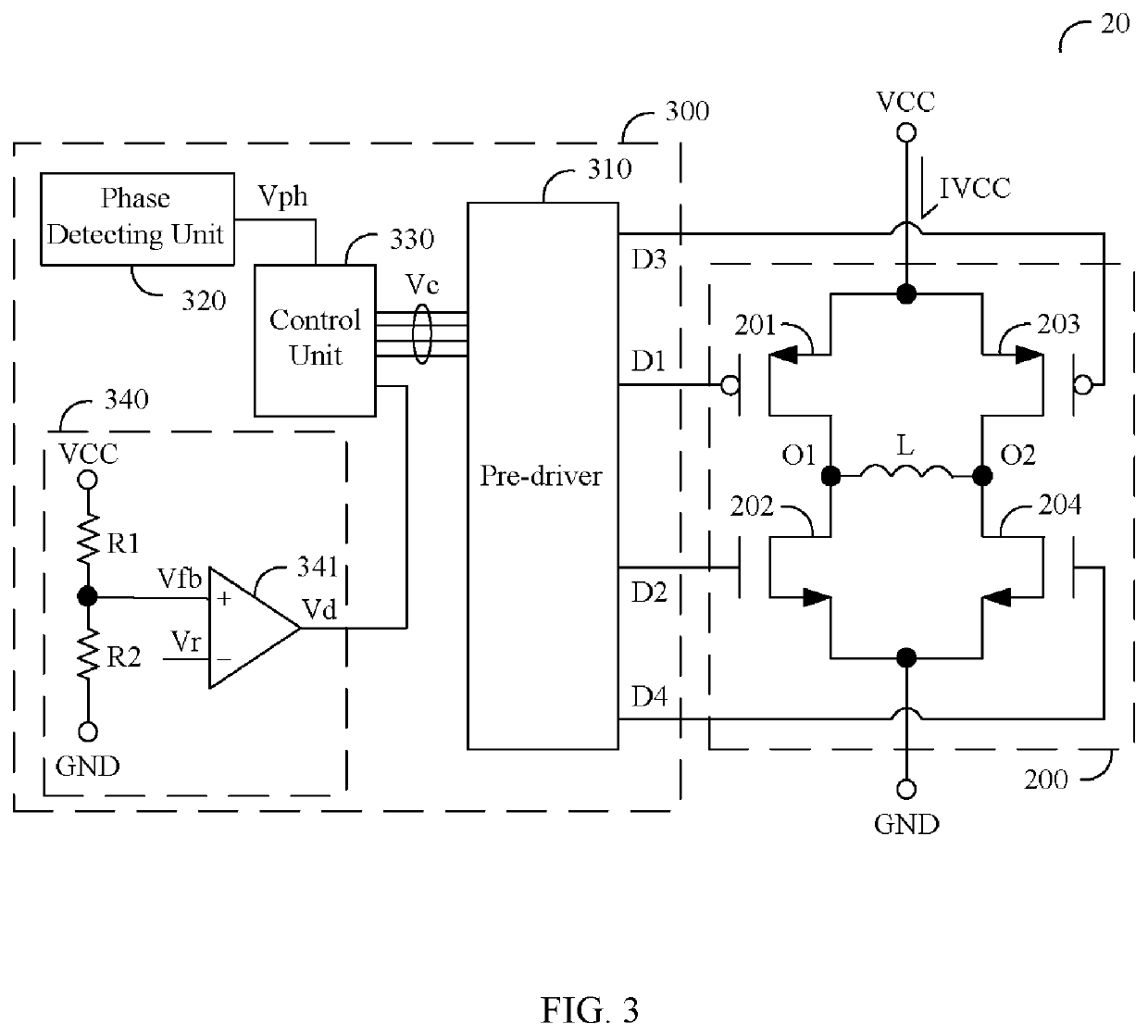
[0016]FIG. 3 is a circuit diagram showing a motor controller 20 and an overvoltage protection circuit 300 according to one embodiment of the present invention. The motor controller 20 is used for driving a motor, where the motor has a motor coil L. The motor coil L has a first terminal O1 and a second terminal O2. The motor controller 20 comprises a switch circuit 200 and the overvoltage protection circuit 300, where the overvoltage protection circuit 300 is coupled to the switch circuit 200 for preventing the switching circuit 200 from damage. The switch circuit 200 is coupled to a terminal VCC and the terminal VCC generates a supply current IVCC to the switch circuit 200. The switch circuit 200 is configured to supply a motor current to the motor coil L, where the motor current may be analogous to the supply current IVCC. The switch circuit 200 includes a first...


PUM


Abstract

An overvoltage protection circuit can be applied to a motor controller. The motor controller is used for driving a motor, where the motor has a motor coil. The motor coil has a first terminal and a second terminal. The motor controller comprises the overvoltage protection circuit and a switch circuit. The switch circuit is an H-bridge circuit and includes two upper-side switches and two lower-side switches. The overvoltage protection circuit comprises a pre-driver, a phase detecting unit, a control unit, and an overvoltage detecting circuit. When an overvoltage occurs at the first terminal or the second terminal, the overvoltage protection circuit is configured to suppress a voltage spike by turning on two upper-side switches or two lower-side switches.

Description

BACKGROUND OF THE INVENTION1. Field of the Invention[0001]The present invention relates to an overvoltage protection circuit, and more particularly, to an overvoltage protection circuit which can be applied to a motor controller.2. Description of the Prior Art[0002]FIG. 1 is a circuit diagram showing a conventional motor controller 10. The motor controller 10 is used for driving a motor, where the motor has a motor coil L. The motor coil L has a first terminal O1 and a second terminal O2. The motor controller 10 comprises a switch circuit 100, a control unit 110, and a phase detecting unit 120. The switch circuit 100 is coupled to a terminal VCC and the terminal VCC generates a supply current IVCC. The switch circuit includes a transistor 101, a transistor 102, a transistor 103, and a transistor 104 for supplying a motor current to the motor coil L. The phase detecting unit 120 generates a phase signal Vph to the control unit 110, so as to inform the control unit 110 to switch phase...

Claims


Application Information

Patent Timeline
IPC IPC(8): H02H7/09
CPCH02H7/09H02H7/0838
Inventor LAI, CHING-FENG
Owner GLOBAL MIXED MODE TECH
Features
  • R&D
  • Intellectual Property
  • Life Sciences
  • Materials
  • Tech Scout
  • Unparalleled Data Quality
  • Higher Quality Content
  • 60% Fewer Hallucinations
Learn More