Temperature control system

a temperature control and temperature control technology, applied in the field of heating and cooling systems, can solve the problems of increasing the average time and causing a lot of disruption in the repair process

Pending Publication Date: 2022-03-17
WARMUP
View PDF0 Cites 0 Cited by
  • Summary
  • Abstract
  • Description
  • Claims
  • Application Information

AI Technical Summary

Benefits of technology

[0027]In preferred embodiments of the invention the support structure comprises perforations that make the support structure breathable. In other words the perforations make the support structure permeable to water. It has been recognized that the perforations can be formed without risk of through-hole bonding. In some embodiments the support structure further comprising a fabric stress mitigation layer on the underside of the structure and the perforations penetrate through the fabric layer but have a diameter of no more than 2 mm, preferably no more than 1 mm. The small diameter of the hole(s) prevents the adhesive from above the structure (i.e. the adhesive that surrounds the thermal elements) from seeping through to the underside of the structure and creating unwanted through-bonds. The advantage of making holes through the main support structure and the stress-mitigation fabric layer is that the holes can then be formed by a straight-forward punching or drilling process after formation and cooling of the support structure. The fabric layer is typically applied to the back of the main support structure while the plastics of the main support structure is still hot so that the fabric layer (typically a polypropylene fleece layer) partially melts and adheres before cooling.
[0028]Alternatively, the structure may comprise a fabric stress mitigation layer on the underside of the structure and also comprise at least one hole through the main support structure that does not penetrate the fabric layer, said hole having a diameter of at least 3 mm, preferably at least 5 mm, more preferably at least 10 mm, and in some embodiments at least 20 mm. The larger hole(s) allows for much more efficient transport of water across the support structure. However, by ensuring that the fabric layer is not penetrated by the large hole, the adhesive on the upper side of the structure is kept separated from the subfloor by the fabric layer so that no through-bonding occurs.

Problems solved by technology

Thus the thermal elements may be squeezed or snapped into position between the projections, but will not easily squeeze back out.
While this wear has not generally been considered to be an issue to date, reducing or removing this installation stress should increase the service life of the product by increasing the average time to failure.
As repairs can be quite disruptive, the service life is an important feature of any such system.

Method used


Image

  • Temperature control system
  • Temperature control system
  • Temperature control system

Examples


Embodiment Construction

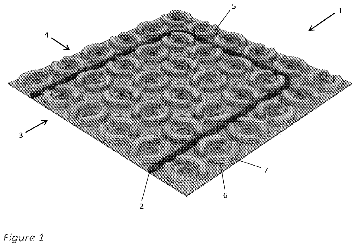
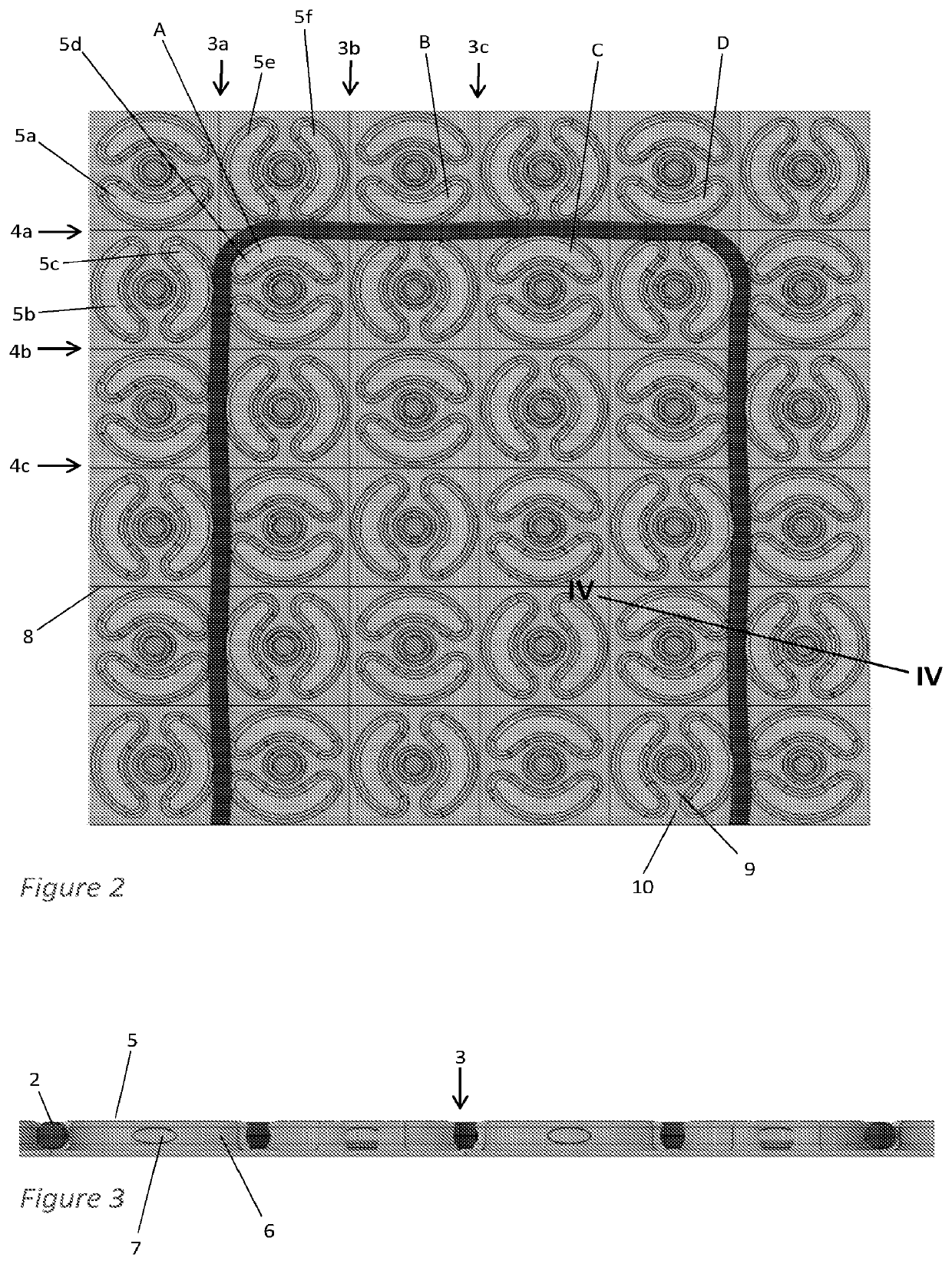
[0062]FIGS. 1-3 show a first embodiment of a castellated support structure 1 in the form of a mat. The mat may take the form of sheets that can be laid adjacent to one another or a roll that can be rolled out onto a desired surface. Either way the mat can be cut to size and shape for any particular installation.

[0063]The mat 1 is typically used as an intermediate structure in underfloor heating installations and provides a structure around which a heating element can be wound while holding the heating element in place. The mat 1 also provides a rigid structure that can protect the heating element from being damaged, e.g. crushed during installation by installers walking around on the mat 1.

[0064]While the remainder of this description discusses a heating element in an underfloor heating installation, it will be appreciated that the mat is equally useful for a cooling element such as a conduit to carry a cold fluid and absorb heat from the room. It will also be appreciated that the i...


PUM


Abstract

A support structure for a heating or cooling system includes a plurality of projections designed to be capable of retaining one or more thermal elements positioned adjacent thereto. The projections are positioned so as to form a first set of substantially parallel undulating channels, each channel having one of the projections forming at least a part of the inner radius of each undulation, with each projection having a recess formed in a side wall thereof facing said channel. The undulations of the channel ensure that a thermal element positioned in the channel will make contact with the projections each time it has to bend around one, without requiring spacing of the projections to squeeze the thermal element. The thermal element can thus be held securely without any play (unwanted lateral movement) in a channel that is slightly wider than the thermal element. Recesses in the channels at the contact points also restrict movement in the vertical direction, thus preventing the thermal element from ‘popping out’ of the channel, while not requiring any restriction narrower than the thermal element.

Description

CROSS-REFERENCE TO RELATED APPLICATIONS[0001]This application is a continuation of U.S. patent application Ser. No. 15 / 919,433, filed on Mar. 13, 2018, which claims priority under 35 U.S.C. § 119 to United Kingdom Patent Application No. 1800924.1 filed on Jan. 1, 2018, the contents of which are hereby incorporated by reference in their entirety.TECHNICAL FIELD[0002]The invention relates to heating and cooling systems for use within floors, walls or ceilings of buildings. In particular it may relate to underfloor heating systems in which heating is provided by heating cables or pipes fitted to a mat or panel.BACKGROUND[0003]Heating and cooling systems which use the floor, wall or ceiling surface as the heat exchange surface require either an embedded heat source or heat sink, commonly in the form of electrically resistive heating cables, or an embedded distribution system of pipes carrying a fluid or gas, that has been either heated or cooled by a connected heat source or heat sink. ...

Claims


Application Information

Patent Timeline
Patent Type & Authority Applications(United States)
IPC IPC(8): F24D13/02F24D3/14F24D3/12
CPCF24D13/024F24D2220/2081F24D3/122F24D3/142Y02B30/00E04C2/52E04C2/525F24D3/141F24D13/022
Inventor WHITE, ANTONYSHEEN, SPENCERANGELOV, SVETOSLAV
Owner WARMUP
Why Eureka
Try Eureka