Occlusal screw, dental implant system and set

Pending Publication Date: 2022-03-24
Z SYST SCHWEIZ
View PDF18 Cites 0 Cited by
  • Summary
  • Abstract
  • Description
  • Claims
  • Application Information

AI Technical Summary

Benefits of technology

[0008]It is an object of the present invention to provide a two-part implant system with an anchoring part and abutment as well as suitable components for such, which overcome the disadvantages of the state of the

Problems solved by technology

However, they have the disadvantage that they are brittle-hard and in contrast to the more ductile metallic implants tend to brittle fracture given a higher mechanical loading, which is also why not all implant shapes can be manufactured without further ado.
Inherent of its design,

Method used


Image

  • Occlusal screw, dental implant system and set
  • Occlusal screw, dental implant system and set

Examples


Example

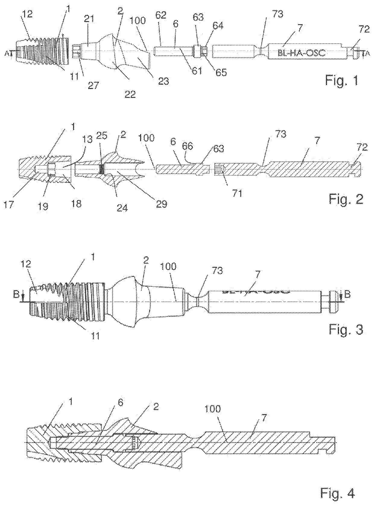
[0037]In the figures, the same reference numerals denote the same or analogous parts.

[0038]The dental implant (anchoring part 1) which amongst others is represented in FIGS. 1-4, has an outer thread 11 that extends almost over the entire length, almost up to the coronal end and that defines an axis 100. The anchoring part 1 has a shape that tapers slightly in the apical direction, so that in cross section along a plane parallel to the axis 100 as a whole with the exception of the thread furrows and apical chip grooves 12 it is curved in a slightly convex manner and, as a whole, merges from a coronally roughly cylindrical shape into an apically tapering shape. The outer thread 11 has a non-constant thread depth and is designed for example in a self-cutting manner.

[0039]A recess 13 into which a fastening post 21 of an abutment 2 projects in the finished implanted state of the implant system is open to the coronal end. The recess forms a coronal support region 18, apically thereof an i...


PUM


Abstract

An occlusal screw for a two-part dental implant system with an anchoring part and an abutment includes a screw head and a screw shank. The screw head apically forms a screw stop. The occlusal screw consists of a ceramic material and has an engagement portion with an outer structure that is not rotationally symmetrical about the screw axis, is cylindrical or conical at least in regions and is suitable for interacting with a corresponding inner structure in a distal recess of a screwing tool, in order to couple the occlusal screw onto the screwing tool in a rotationally fixed manner. A design concerning which the engagement portion occlusally includes a cylindrical region and apically thereof a clamping region, which continuously widens in the apical direction, is particularly advantageous. The clamping region can be for example conical.

Description

BACKGROUND OF THE INVENTIONField of the Invention[0001]The invention relates to the field of medical technology. It relates to an occlusal screw, a ceramic dental implant system as well as to a set.Description of Related Art[0002]Amongst dental implant systems, two-part implant systems are widespread. These comprise the actual implant (also called “anchoring part” or, if it is provided with a thread, “screw”) and an attachment part (“abutment”) which is provided for fastening thereto. The anchoring part can herein be designed such that it is incorporated roughly level with the bone surface (as a so-called bone-level implant), or it can be provided with a region coronally of the bone surface, said region often being widened with respect to the enossal region that is generally provided with a thread, sometimes being denoted as a tulip and being provided for reaching roughly to the gum surface. Implants with such a transgingival region are called tissue level implants. The region (“pos...

Claims


Application Information

Patent Timeline
IPC IPC(8): A61C8/00
CPCA61C8/0068A61C8/0012A61C8/0069A61C8/0089A61C8/0022A61C8/0054A61C8/006
Inventor THOMKE, ERNSTTHEUBET, CLAUDE
Owner Z SYST SCHWEIZ
Why Eureka
Try Eureka