Device comprising a receptacle for storing a liquid

Pending Publication Date: 2022-03-24
FRANCK JAN
View PDF19 Cites 0 Cited by
  • Summary
  • Abstract
  • Description
  • Claims
  • Application Information

AI Technical Summary

Benefits of technology

[0034]If the thermal insulation panels are covered by a vapour barrier, especially at their inner sides facing towards the interior of the chamber, the insulation can be prevented from moisture. For example, a metal foil coukd be used as a vapour barrier.
[0035]The invention can be further improved in that the thermal insulation panels are covered by a metal foil or by another barrier for thermal radiation. By doing this, not only a flow of heat to the outside and a convection betwee

Problems solved by technology

However, such containers are in most cases relatively expensive, inter alia also because the outer surface of containers is often curved, for example following cylindrical or calotte-shaped surfaces, so that the insulating material needs to be adapted to such surface in respect of its shape.
Furthermore, the insulation on the outer surface of the container hinders a maintenance person from gaining access to the outer surface of the container, especially for inspecting it, for example in view of leakages or rust.
This arrangement has a number of drawbacks: First of all, the outer surface of the container is not accessible for inspection due to the stones surrounding it; furthermore, a chamber housing such liquid container and such receptacle for stones does not comprise any thermal insulation and therefore, much heat is dissipated even if no heat is requested.
Therefore, the heating action cannot be controlled, and at any time, there is a loss of heat through the uninsulated bottom and walls of the underground storage room.
Therefore, the insulation of the underground room is bypassed by such air ducts, and hence the insulation is not able to keep the liquid inside of the container at a constant temperature.
Although the underground room of the building

Method used


Image

  • Device comprising a receptacle for storing a liquid

Examples


Example

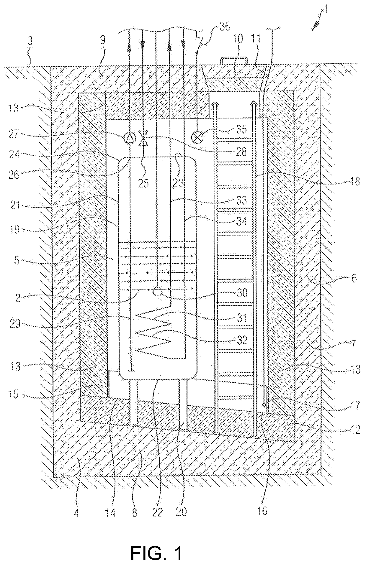
[0056]The equipment 1 for the storage of a liquid 2 to be kept at temperature exemplarily represented by the drawing may be located below the ground surface 3. However this is not mandatory. The entire arrangement could—with the exception of a foundation 4 or some other substructure—also be placed above the ground surface 2.

[0057]A distinctive characteristic of the equipment 1 according to the invention is a chamber 5, which is delimited by an enclosure 6.

[0058]This enclosure 6 preferably consists of walls 7, a floor 8, and a ceiling 9. Walls 7, floor 8, and ceiling 9 should be planar and are preferably at least self-supporting. For these purposes multifarious materials providing sufficient stability come into question. Preferred however are building materials such as bricks, stone, or concrete; of course also other materials are principally possible like plastics, metals, or even wood, although such materials are generally inferior to inorganic, nonmetallic building materials in re...


PUM


Abstract

The invention refers to an equipment (1) including a container (19) for the storage of a liquid (2) as well as thermal insulation panels (12,13), wherein none of the thermal insulation panels (12,13) is mounted directly on or even in contact with an outer surface of the container (19), wherein a chamber (5) housing the container (19) is delimited by an enclosure (6) consisting of walls (7), a floor (8) and a ceiling (9), and which is accessible through an access opening, either in the form of an entrance opening in one of the walls (7) closeable by a door or in the form of a manhole (11) eccentric to the center of the ceiling (9) and closeable by a lid (10), wherein the lid (10) or the door is thermally insulated at the inner side and is provided with an air-tight sealing all around, and wherein an inner surface of the chamber (5) except the access opening is entirely covered with the thermal insulation panels (12,13) in such a way that a volume of space occupied by the container (19) is smaller than a volume of space delimited by the inner sides of the thermal insulation panels (12,13) at the inner side of the walls (7), the ceiling (9) and the floor (8), leaving a space for maintenance between the outer surface of the container (19) and the thermal insulation panels (12,13) mounted to the inner surface of the chamber (5), which is only filled with air and is free of any liquid or bulk material in order to keep the container and the bottom of the chamber visible for inspection, and wherein the only way for heat to leave the air-filled space for maintenance between the outer surface of the container (19) and the thermal insulation panels (12,13) is through these thermal insulation panels (12,13) and neither besides such thermal insulation panels (12,13) nor through any kind of air duct or acitve or passive venting.

Description

REFERENCE TO PENDING PRIOR PATENT APPLICATIONS[0001]This patent application:[0002](i) is a continuation-in-part of pending prior U.S. patent application Ser. No. 16 / 541,307, filed Aug. 15, 2019 by Jan Franck for DEVICE COMPRISING A RECEPTACLE FOR STORING A LIQUID (Attorney's Docket No. KUCH-74 CIP), which patent application, in turn:[0003](a) is a continuation-in-part of prior U.S. patent application Ser. No. 15 / 111,398, filed Jul. 13, 2016 by Jan Franck for DEVICE COMPRISING A RECEPTACLE FOR STORING A LIQUID (Attorney's Docket No. KUCH-74), which patent application, in turn:[0004](1) is a 371 national stage entry of International (PCT) Patent Application No. PCT / IB2015 / 000021, filed Jan. 14, 2015 by Jan Franck for DEVICE COMPRISING A RECEPTACLE FOR STORING A LIQUID, which in turn claims benefit of:[0005](A) German Patent Application No. DE 10 2014 000 191.1, filed Jan. 14, 2014.[0006]The four (4) above-identified patent applications are hereby incorporated herein by reference.FIELD...

Claims


Application Information

Patent Timeline
IPC IPC(8): B65D88/76B65D90/00B65D90/10B65D88/74B65D90/06B65D90/02
CPCB65D88/76B65D90/008B65D90/028B65D88/744B65D90/06B65D90/105F28D20/0043F28D2020/0078Y02E60/14
Inventor FRANCK, JAN
Owner FRANCK JAN
Why Eureka
Try Eureka