Wet friction disc

a technology of friction discs and friction plates, applied in the field of wet friction discs, can solve problems such as the decrease of responsiveness, and achieve the effect of reducing uneven wear of the mating member

Active Publication Date: 2022-03-24
JTEKT CORP +1
View PDF2 Cites 1 Cited by
  • Summary
  • Abstract
  • Description
  • Claims
  • Application Information

AI Technical Summary

Benefits of technology

[0011]According to the aspect, the present disclosure can provide a wet friction disc that can discharge the lubricant toward the outer circumferential side more efficiently and mitigate uneven wear of the mating member.

Problems solved by technology

When such surface irregularities develop, the lubricating oil may be discharged less efficiently at the time of transition from the frictionally-engaged state to the non-frictionally-engaged state and vice versa, resulting in a decrease in responsiveness.

Method used


Image

  • Wet friction disc
  • Wet friction disc
  • Wet friction disc

Examples


first embodiment

[0025]An embodiment of the present disclosure will be described with reference to FIG. 1 to FIG. 8. The embodiment to be described below will be shown as a specific example suitable for implementing the present disclosure. While some part of the embodiment specifically illustrates various technical items that are technically preferred, the technical scope of the present disclosure is not limited to such specific aspects.

[0026]Braking Device 10

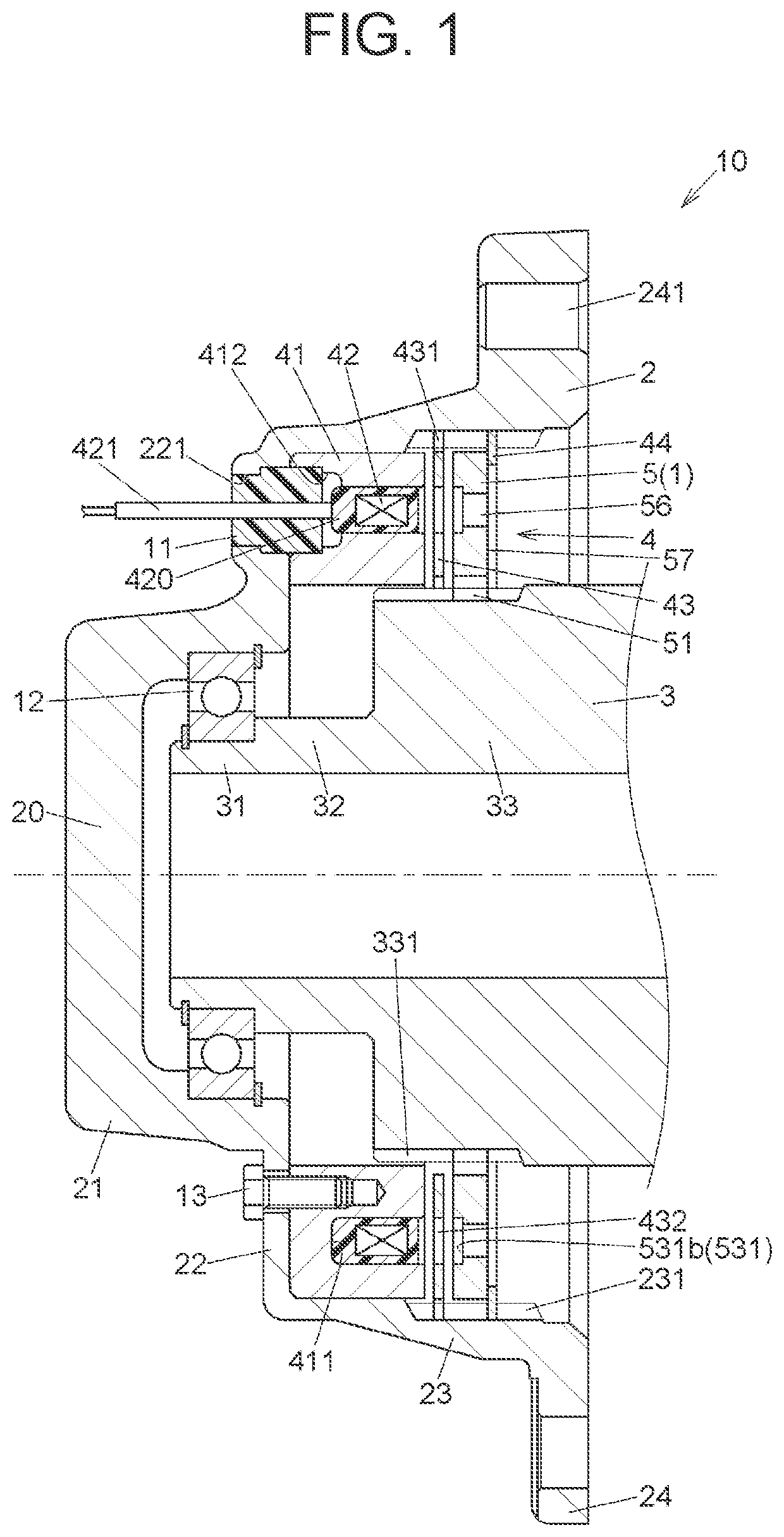
[0027]A braking device 10 as a friction engaging device including a wet friction disc 1 of the embodiment will be described. Hereinafter, a direction in which a central axis of the wet friction disc 1, i.e., an armature 5, to be described later, extends will be referred to as an axial direction. A radial direction of the wet friction disc 1 will be referred to simply as a radial direction and a circumferential direction of the wet friction disc 1 will be referred to simply as a circumferential direction.

[0028]FIG. 1 is a sectional view of the b...

second embodiment

[0081]This embodiment is an example in which the wet friction disc 1 is used in a clutch device 100 as a friction engaging device. FIG. 9 is a sectional view showing the overall structure of the clutch device 100 of this embodiment. FIG. 10 is an enlarged view around a pilot clutch 8 of FIG. 9. FIG. 11 is a front view of a pilot outer plate 84 as the wet friction disc 1 of this embodiment and an enlarged view of part of the pilot outer plate 84.

[0082]The clutch device 100 of this embodiment is a clutch of an electronically controlled 4WD coupling (so-called intelligent torque controlled coupling (ITCC) (R)) type, and is disposed between a propeller shaft and a rear differential device in a four-wheel-drive vehicle to allow or interrupt transmission of a rotary force between the propeller shaft and the rear differential device. Thus, the clutch device 100 switches between a four-wheel-drive state in which the driving power of the engine is transmitted to front wheels and rear wheels ...


PUM


Abstract

A wet friction disc includes a lubrication groove and a plurality of lands defined by the lubrication groove. The lubrication groove has a plurality of circumferential groove portions that extends in a circumferential direction and has a predetermined groove width in a radial direction, and a plurality of intersecting groove portions that extends in directions intersecting the circumferential direction. At least some of the circumferential groove portions have an arc shape such that an end in the circumferential direction is located adjacent to one of the lands in the circumferential direction and that the groove width is entirely contained within a range in the radial direction spanned by that land.

Description

CROSS-REFERENCE TO RELATED APPLICATION[0001]This application claims priority to Japanese Patent Application No. 2020-158688 filed on Sep. 23, 2020, incorporated herein by reference in its entirety.BACKGROUND1. Technical Field[0002]The present disclosure relates to a wet friction disc.2. Description of Related Art[0003]Wet friction discs that slide on a mating member in an environment where a lubricant is present are used for vehicles, for example, in a clutch device that transmits torque between rotating members of a driving system and in a braking device that brakes the rotation of rotating members. For example, Japanese Unexamined Patent Application Publication No. 2016-211713 (JP 2016-211713 A) discloses a device that includes an inner plate and an outer plate as wet friction discs capable of switching between a state of being frictionally engaged with each other and a state of not being frictionally engaged with each other in an environment where a lubricant is present, and that...

Claims


Application Information

Patent Timeline
Patent Type & Authority Applications(United States)
IPC IPC(8): F16D13/74F16D13/64
CPCF16D13/74F16D13/64F16D65/12F16D65/14F16N1/00F16D2121/20F16D13/648F16D27/112F16D2023/123B60T1/062F16D55/38F16D2125/36F16D2065/1332F16D65/127F16D65/128
Inventor TAKEUCHI, YOSHIKITAKUNO, HIROSHIKAMIMURA, KAZUAKINAKAMURA, TAKESHIYOSHIMURA, TAKAHIRO
Owner JTEKT CORP
Why Eureka
Try Eureka