Double-side or one-side machining machine

a machining machine and one-side technology, applied in the direction of lapping machines, grinding machine components, manufacturing tools, etc., can solve the problem that it is not possible to rotate only the counter bearing element or the first working disk, and achieve the effect of convenient, reliable and flexible operation

Pending Publication Date: 2022-03-31
PETER WOLTERS GMBH
View PDF2 Cites 0 Cited by
  • Summary
  • Abstract
  • Description
  • Claims
  • Application Information

AI Technical Summary

Benefits of technology

[0011]Proceeding from the explained prior art, the object of the invention is therefore to provide a double-side or one-side machining machi

Problems solved by technology

It is, however, possible to only rotatably drive eith

Method used


Image

  • Double-side or one-side machining machine
  • Double-side or one-side machining machine

Examples


Embodiment Construction

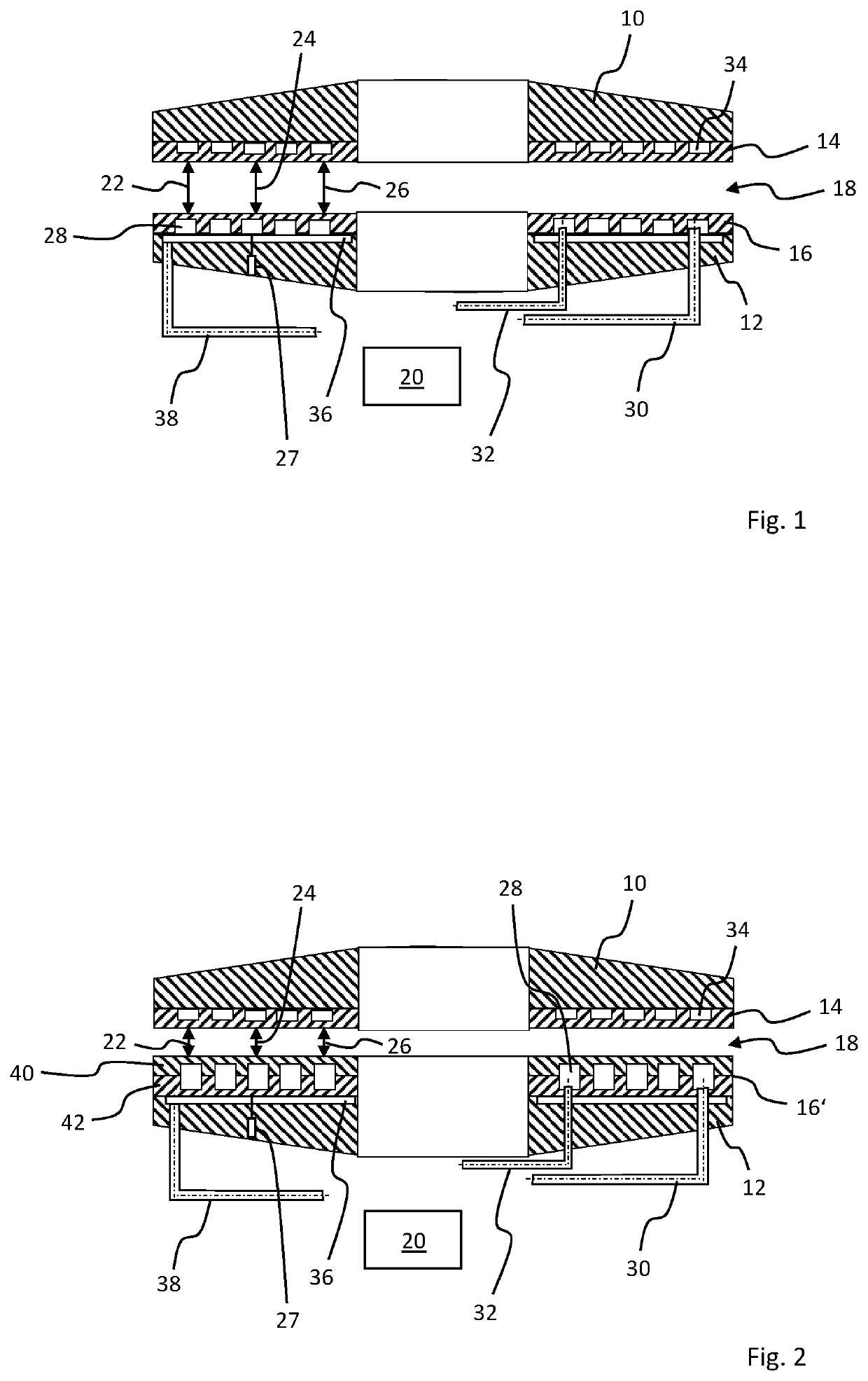
[0043]The double-side machining machine depicted merely as an example in FIG. 1 has an annular first, bottom support disk 12 and a second, top support disk 10 that is also annular. An annular first, bottom working disk 16 is fastened to the bottom support disk 12, and a second, top working disk 14 that is also annular is fastened to the top support disk 10. Between the annular working disks 14, 16, an annular working gap 18 is formed in which flat workpieces such as wafers are machined on both sides during operation. The double-side machining machine can for example be a polishing machine, lapping machine, or a grinding machine.

[0044]The top support disk 10, and with it the top working disk 14, and / or the bottom support disk 12 and with it the bottom working disk 16, can be rotatably driven relative to each other by a suitable drive apparatus comprising for example a top drive shaft, and / or a bottom drive shaft, as well as at least one drive motor. The drive apparatus is known per s...


PUM


Abstract

A machining machine comprises a first support disk, a first working disk coupled to the first support disk, and a counter bearing element positioned to define a working gap between the first working disk and the counter bearing element. The first working disk and the counter bearing element are configured to rotate relative to each other to machine at least one side of a flat workpiece. A pressure volume is positioned between the first support disk and the first working disk and is configured to hold a pressure fluid, which generates a pressure configured to deform the first working disk. One or more temperature-controlling channels are positioned within the first working disk and configured to hold a temperature-controlling fluid that is configured to control a temperature of the first working disk, wherein the one or more temperature-controlling channels are fluidly separate from the pressure volume.

Description

CROSS REFERENCE TO RELATED INVENTION[0001]This application is based upon and claims priority to, under relevant sections of 35 U.S.C. § 119, German Patent Application No. 10 2020 125 246.3, filed Sep. 28, 2020, the entire contents of which are hereby incorporated by reference.TECHNICAL FIELD[0002]The invention relates to a double-side or one-side machining machine with a preferably annular first working disk which is fastened to a first support disk, and with a counter bearing element, wherein the first working disk and the counter bearing element can be driven to rotate relative to each other by at least one drive shaft, wherein a working gap is formed between the first working disk and the counter bearing element to machine both sides or one side of flat workpieces, wherein a pressure volume is arranged between the first support disk and the first working disk and is connected to a pressure fluid supply which can be actuated such that a pressure is built up in the pressure volume ...

Claims


Application Information

Patent Timeline
IPC IPC(8): B24B51/00B24B7/10
CPCB24B51/00B24B7/10B24B49/08B24B49/14B24B37/08B24B37/10B24B7/16B24B7/17H01L21/67092
Inventor BOLLER, HANS-PETERNEUBER, INGO
Owner PETER WOLTERS GMBH
Why Eureka
Try Eureka