A hydraulic continuous variable speed system having hydraulic and pneumatic speed controls and a method of use

a continuous variable speed and control technology, applied in the direction of machines/engines, greenhouse gas reduction, gearing, etc., can solve the problems of limited control modes, complex and expensive designs, etc., and achieve the effect of reducing load erraticism

Pending Publication Date: 2022-03-31
PROSTO WIND POWER
View PDF8 Cites 0 Cited by
  • Summary
  • Abstract
  • Description
  • Claims
  • Application Information

AI Technical Summary

Benefits of technology

[0006]The present invention provides a pneumatically-assisted, hydraulic CVT that does not require pumps, pistons, gears, belts, pulleys, clutches, or valves to vary the hydraulic fluid pressure for operation. One part of the control of operation is with a programmable logic controller, or similar device or means that monitors the output of the inverter output to electrical load / line and then controls the system, including both hydraulic and pneumatic aspects, for variable speed control of the CVT to produce a reactive balance electrical source and minimize load erraticism.

Problems solved by technology

However, a need exists for improvements in CVT given their mechanically complex and expensive designs and limited modes of control.

Method used


Image

  • A hydraulic continuous variable speed system having hydraulic and pneumatic speed controls and a method of use
  • A hydraulic continuous variable speed system having hydraulic and pneumatic speed controls and a method of use
  • A hydraulic continuous variable speed system having hydraulic and pneumatic speed controls and a method of use

Examples


Embodiment Construction

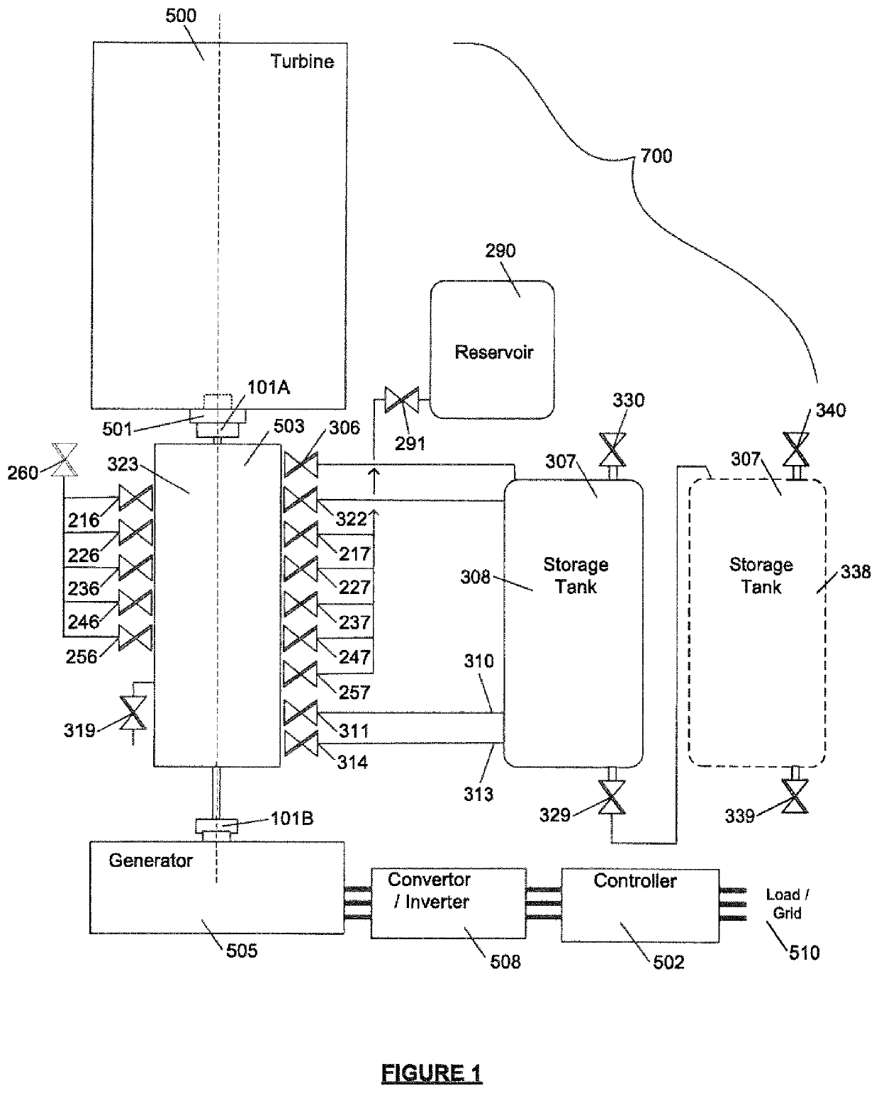
[0024]FIG. 1 illustrates an embodiment of system 700 that includes a turbine or wind engine 500, an integrated pneumatically-assisted hydraulic CVT 503, and a generator 505. The CVT 503 is positioned between the engine 500 and generator 505. The CVT has shaft adapters 101A and 101B for connection to the engine 500 and generator 505, respectively. A tachometer 501 may be added for pneumatic safety brake operation is so desired.

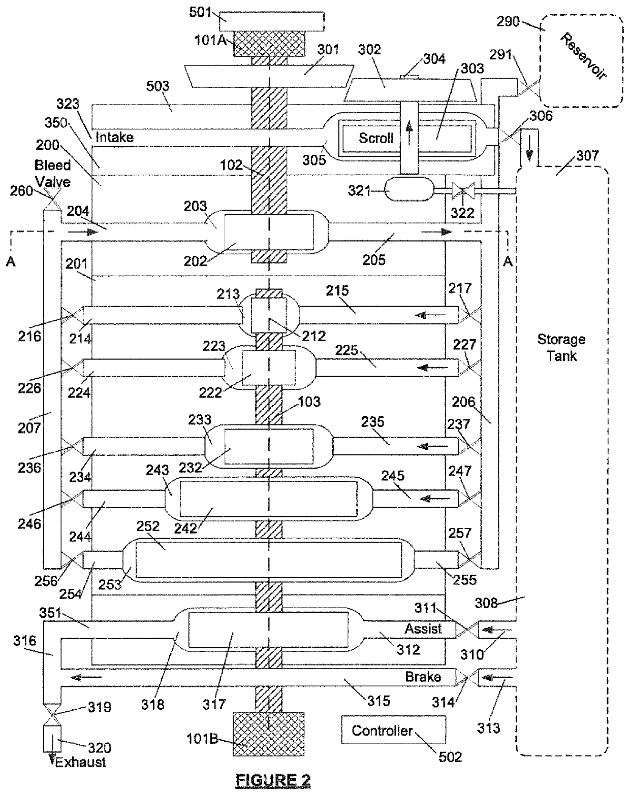
[0025]The CVT has a series of hydraulic valves 216, 217, 226, 227, 236, 237, 246, 247, 256, and 257. These valves provide selection of primary hydraulic chambers for speed control. Pneumatic control valves 306, 311, 314, and 319 are also provided and these valves provide secondary assistance to speed control of the CVT 503.

[0026]Hydraulic reservoir 290 is provided with valve 291. The hydraulic reservoir 290 supplies hydraulic fluid for operation. Also included as part of the system are a plurality of pneumatic storage tanks, two provided as 308 and 338, but add...


PUM


Abstract

A hydraulic continuous variable transmission is provided to connect a wind turbine and a generator. The hydraulic continuous variable transmission has a primary paddle wheel and a number of secondary paddle wheels for macro speed control. Also provided are pneumatic paddle wheels for micro speed control. A controller is included that measures AC electrical characterized output to load or line for speed control.

Description

FIELD OF THE INVENTION[0001]This invention relates to a system using a continuous variable transmission with pneumatic assist for micro level speed control and optimizing power generation from a turbine (wind or water) by evaluating AC electrical characteristics at the load / line after accomplishing energy generation of an entire power arrangement.BACKGROUND OF THE INVENTION[0002]Continuous variable transmissions (CVT) are known and have been used in bicycles, motor vehicles, winches, hoists, for power transfer, and the like. There are many variations of design that have been developed for these devices, and types include variable diameter pulleys with belts, toroidal or roller based, friction based, hydrostatic based, ratcheting based, magnetics, etc.[0003]Examples of United States patents that relates to CVT include U.S. Pat. Nos. 4,565,110, 4,970,862, 4,945,482, 4,922,717, 5,072,587, 4,916,900, 4,914,914, 4,850,192, and 4,838,024, all of which are hereby incorporated in their enti...

Claims


Application Information

Patent Timeline
Patent Type & Authority Applications(United States)
IPC IPC(8): F03D15/00F03D7/02F03D9/11F16H7/08F16H9/12F16H47/02
CPCF03D15/00F03D7/02F03D9/11F16H7/08F05B2260/40F16H47/02F05B2220/30F05B2220/706F16H9/12F16H61/48F16H41/02F16H47/06Y02E70/30F05B2210/16F03D7/0276F05B2260/406Y02E10/72Y02E60/16
Inventor HIRSH, DOUGLAS S.HRINDA, RADOVAN
Owner PROSTO WIND POWER
Why Eureka
Try Eureka