Pin driver and test equipment calibration

a technology of test equipment and driver, which is applied in the direction of electronic circuit testing, measurement devices, instruments, etc., to achieve the effects of maximizing the functional test range of the system, minimizing loading effects, and being easy to produ

Active Publication Date: 2022-03-31
ANALOG DEVICES INC
View PDF7 Cites 1 Cited by
  • Summary
  • Abstract
  • Description
  • Claims
  • Application Information

AI Technical Summary

Benefits of technology

[0005]The present inventors have recognized, among other things, that a problem to be solved includes providing a packaged automated test system configured to provide driver, comparator, active load, and per-pin parametric measurement functions. The inventors have recognized the problem includes accommodating the speed and accuracy requirements of, for example, the driver, comparator, and active load circuitry using integrated device structures that occupy minimal die area, while minimizing loading effects at an interface with a device under test (DUT), and while maximizing a functional test range of the system. The problem can include providing a system that is relatively small, inexpensive to produce, consumes less power than traditional systems, or provides higher fidelity performance relative to traditional systems.

Problems solved by technology

The problem can include providing a system that is relatively small, inexpensive to produce, consumes less power than traditional systems, or provides higher fidelity performance relative to traditional systems.
However, various problems can arise with such switches, including switch size, resistance, loading on the DUT pin, and calibration range.

Method used


Image

  • Pin driver and test equipment calibration
  • Pin driver and test equipment calibration
  • Pin driver and test equipment calibration

Examples


Embodiment Construction

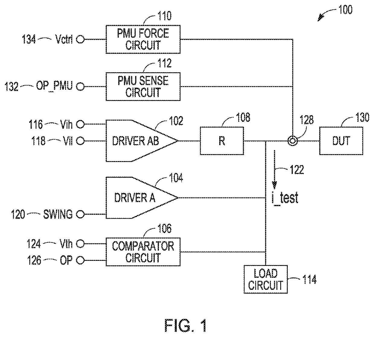
[0018]A test system, such as a force-sense test system for use with automated test equipment (ATE), can be configured to provide a voltage or current stimulus to a device under test (DUT) at a specified time, and optionally can measure a response from the DUT. The test system can be configured to provide high fidelity output signal pulses over a relatively large output signal magnitude range to accommodate different tests and different types of devices under test.

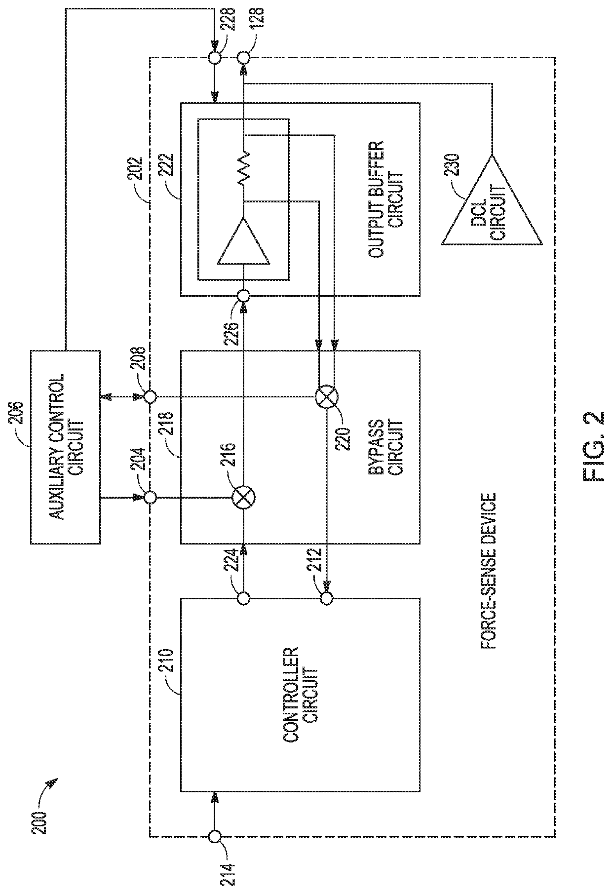
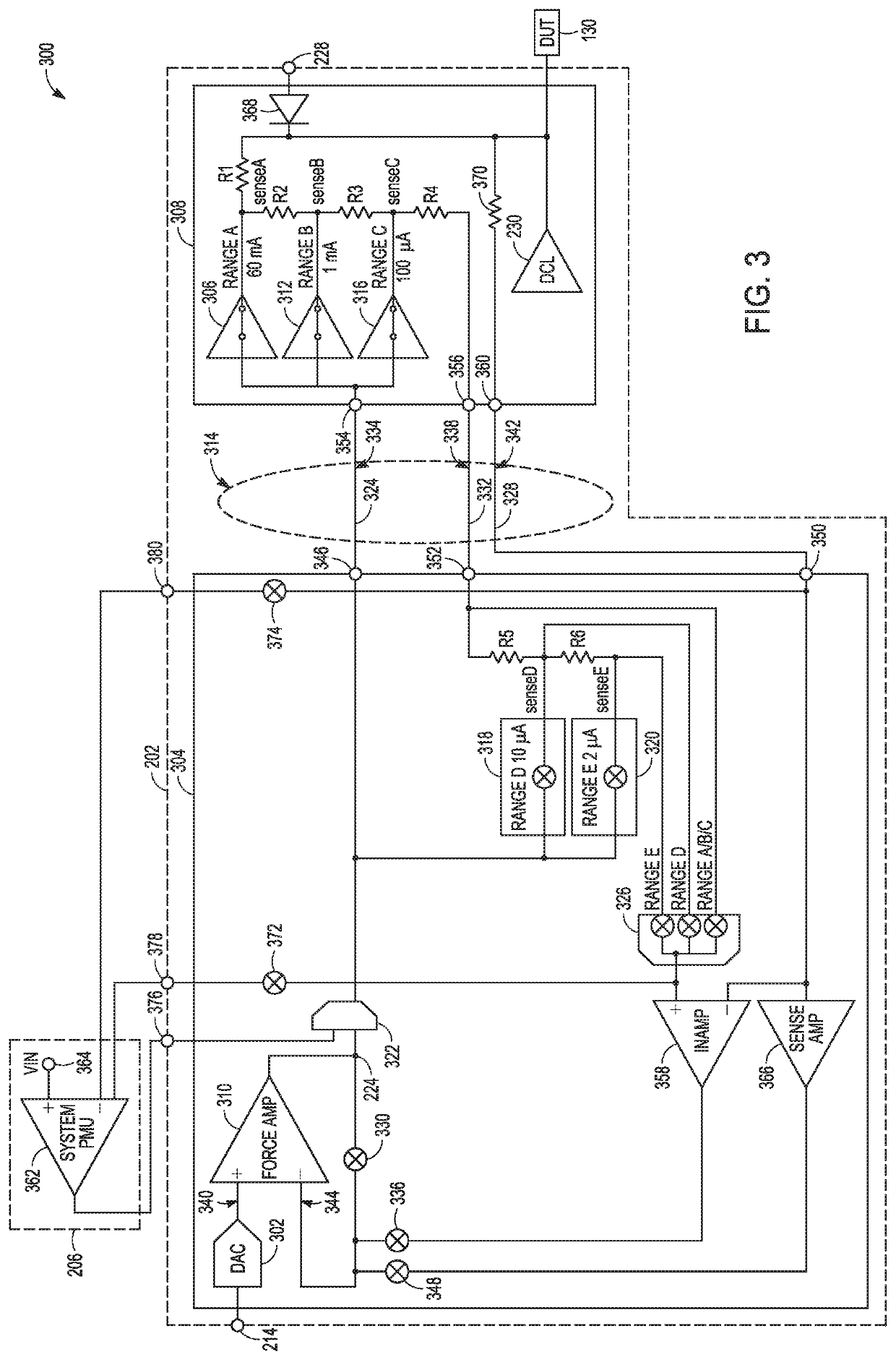
[0019]In an example, a force-sense system, or force-sense measurement device, can include a pin driver architecture that can provide high fidelity stimulus signals with minimal overshoot or spiking of high frequency current signals, and can enhance pulse edge placement accuracy and signal bandwidth at high or low power operating levels. The test system can include a single-package ATE solution that can include, among other things, a driver circuit, comparator circuit, and active load circuit, and a per-pin parametric measur...


PUM


Abstract

A force-sense system can provide signals to, or receive signals from, a device under test (DUT) at a first DUT node. The system can include output buffer circuitry configured to provide a DUT signal to the DUT in response to a force control signal at a buffer control node, and controller circuitry configured to provide the force control signal at the buffer control node. The system can include bypass circuitry configured to selectively bypass the controller circuitry and provide an auxiliary control signal at the buffer control node. The auxiliary control signal can be used for system calibration. In an example, an external calibration circuit can provide the auxiliary control signal in response to information received from the DUT.

Description

CROSS-REFERENCE TO RELATED APPLICATIONS[0001]This patent application is a continuation-in-part of, and claims the benefit of priority of, U.S. patent application Ser. No. 17 / 038,598, entitled “Partitioned Force-Sense System for Test Equipment,” filed on Sep. 30, 2020 (Attorney Docket No. 3867.757US1), which is hereby incorporated herein by reference in its entirety.BACKGROUND[0002]A test system for electronic device testing can include a pin driver circuit that provides a voltage test pulse to a device under test (DUT). In response, the test system can be configured to measure a response from a DUT, such as to determine whether the DUT meets one or more specified operating parameters. A test system can optionally include multiple different classes of driver circuits to provide circuit test signals having different amplitude or timing characteristics. In an example, the test system is configured to measure a response from a DUT using an active load and a comparator circuit to sense t...

Claims


Application Information

Patent Timeline
Patent Type & Authority Applications(United States)
IPC IPC(8): G01R31/317G01R31/319G01R31/26
CPCG01R31/31713G01R31/31723G01R31/2632G01R31/3191G01R31/31926
Inventor SINGH, AMIT KUMARMCQUILKIN, CHRISTOPHER C.CAREY, BRIAN
Owner ANALOG DEVICES INC
Why Eureka
Try Eureka