Storage system and control method therefor
- Summary
- Abstract
- Description
- Claims
- Application Information
AI Technical Summary
Benefits of technology
Problems solved by technology
Method used
Image

Examples
first embodiment
(1) First Embodiment
(1-1) Configuration of Information Processing System According to Present Embodiment
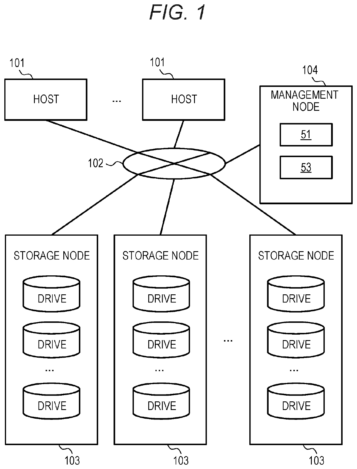
[0043]FIG. 1 illustrates a configuration example of an information processing system according to the present embodiment.
[0044]This information processing system includes a plurality of host devices 101, a plurality of storage nodes 103, and a management node 104 connected to each other via a network 102 configured using, for example, a fiber channel, Ethernet (registered trademark), a local area network (LAN), or the like.
[0045]The host device 101 is a general-purpose computer device that transmits a read request or a write request (hereinafter, as appropriate, collectively referred to as an input / output (I / O) request) to the storage node 103 in response to a user's operation or a request from a mounted application program. Note that the host device 101 may be a virtual computer device such as a virtual machine.
[0046]Specifically, for example, the storage node 103 is a physical s...
second embodiment
(2) Second Embodiment
[0107]A second embodiment will be described. A difference from the first embodiment will be mainly described, and common points with the first embodiment will be omitted or simplified.
[0108]In the present embodiment, each redundancy group is constituted by quadruple SCs. That is, the redundancy group is constituted by one SC (A) and three SCs (S) in the present embodiment.
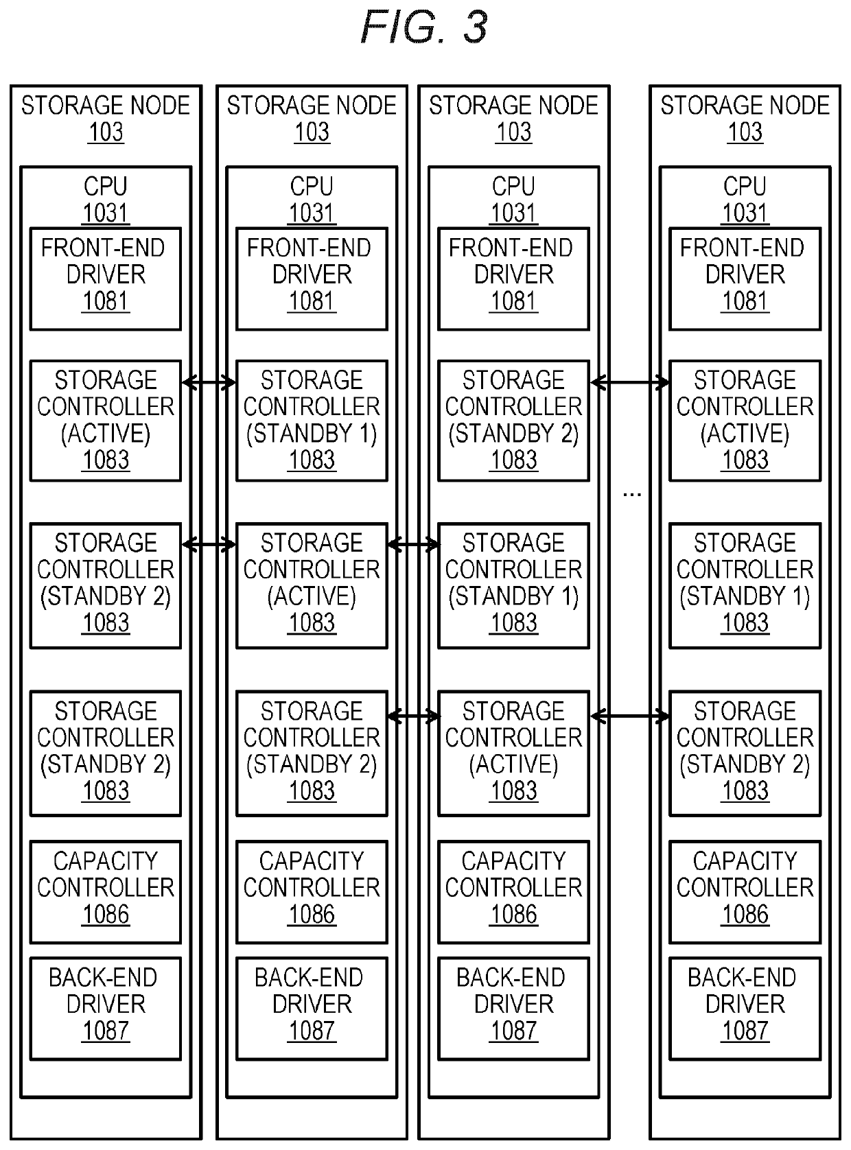
[0109]FIG. 17 illustrates a logical configuration example of the storage node 103 according to the second embodiment. A difference from FIG. 3 is that the redundancy group is constituted by four SCs. There are four SCs on each node.
[0110]Here, the following concept of “influential node” is defined for each SC. Hereinafter, N is the number of SCs (S). In the present embodiment, N=3. Hereinafter, m is a standby number. α or β=X, Y, Z, and so on.[0111]A storage node where an SC-α (A) is arranged is a zeroth-order influential node of SC-α.[0112]A storage node where an SC-α (Sm) is arranged is an m-...
third embodiment
(3) Third Embodiment
[0126]A third embodiment will be described. A difference from the first and second embodiments will be mainly described, and common points with the first and second embodiments will be omitted or simplified.
[0127]In the third embodiment, a quintuple redundancy group is adopted.
[0128]FIG. 23 illustrates an example of SC arrangement according to the third embodiment. There are four SCs (S), and X1=4, X2=3, X3=2, and X4=1 according to the example in FIG. 23. FIG. 24 illustrates an example when Node 2 becomes a tertiary failure root node. The influential nodes are seven nodes (Nodes 1, 2, 4, 5, 6, 9, and 10), and there is no redundancy group in which four or more SCs (S) are arranged in these seven nodes, so that the SC arrangement condition is satisfied in the present embodiment. An arrangement method illustrated in FIGS. 21 and 23 can be generalized to N−multiplexing, and the arrangement condition of the present embodiment is satisfied by setting a value of Xi to X...
PUM
 Abstract
Description
Claims
Application Information
 - R&D
- Intellectual Property
- Life Sciences
- Materials
- Tech Scout
- Unparalleled Data Quality
- Higher Quality Content
- 60% Fewer Hallucinations
Browse by: Latest US Patents, China's latest patents, Technical Efficacy Thesaurus, Application Domain, Technology Topic, Popular Technical Reports.
© 2025 PatSnap. All rights reserved.Legal|Privacy policy|Modern Slavery Act Transparency Statement|Sitemap|About US| Contact US: help@patsnap.com