Appliance Immersion Cooling System

a technology of immersion cooling and cooling fluid, which is applied in the direction of electrical equipment, electrical apparatus, electrical apparatus contruction details, etc., can solve the problems of insufficient draining of cooling fluid, inherently limited operating capabilities, and the nature and cost of the chosen cooling fluid, fluorocarbon liquid, etc., to avoid unnecessary proliferation of numbers

Pending Publication Date: 2022-03-31
BOYD CHRISTOPHER L +6
View PDF5 Cites 2 Cited by
  • Summary
  • Abstract
  • Description
  • Claims
  • Application Information

AI Technical Summary

Benefits of technology

[0026]FIG. 13 illustrates, in control schematic form, one instantiation of a flow control facility suitable for implementing our invention.
[0027]In the drawings, similar elements will be similarly numbered whenever possible. However, this practice is simply for convenience of reference and to avoid unnecessary proliferation of numbers, and is not intended to imply or suggest that our invention requires identity in either function or structure in the several embodiments.

Problems solved by technology

One particular problem in the vertical-stack-type systems disclosed in the above references is the necessity of draining the cooling fluid whenever physical access to the electronic modules was required.
In general, such an operation, besides being time consuming, requires the entire system to be switched off, especially if the component requiring attention is an essential element in the system architecture, such as the central processing unit (“CPU”).
As noted by the author, the lack of supplemental apparatus in the Puget system to extract waste heat from the oil inherently limited its operating capabilities.
Another problem with the Cray Research systems in particular is the nature and cost of the chosen cooling fluid: fluorocarbon liquids.
As is known, other dielectric fluids, such as mineral oil, have better heat transfer characteristics; of course, being an oil, the use thereof does represent a greater residue problem on modules that may be repairable.
Although an improvement in several respects over the prior art discussed above, this system exhibits, inter alia, the following problems: generally non-uniform flow patterns through the several appliance slots within the tank, potentially resulting in uneven cooling across all slots; constricted dielectric fluid supply and return ports resulting in unnecessarily high fluid flow velocities at the respective points of connection to the tank; poor scalability; and inadequate attention to fail-soft operation.

Method used


Image

  • Appliance Immersion Cooling System
  • Appliance Immersion Cooling System
  • Appliance Immersion Cooling System

Examples


Embodiment Construction

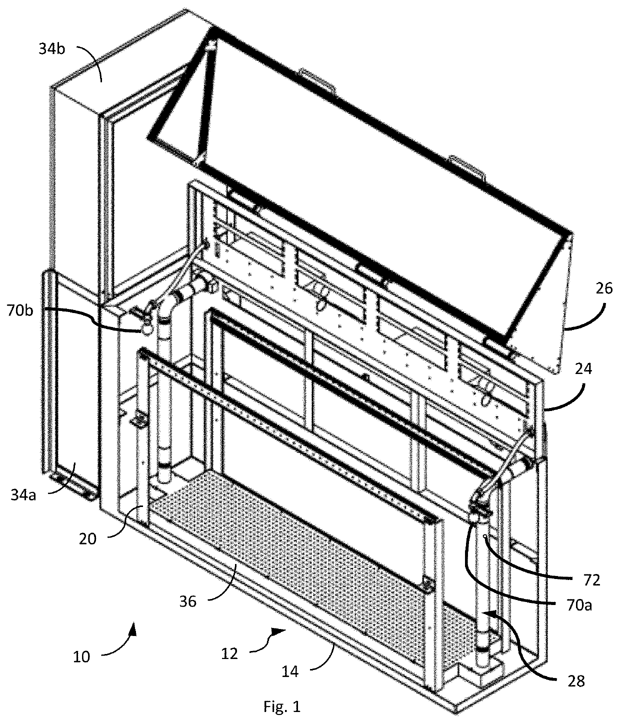
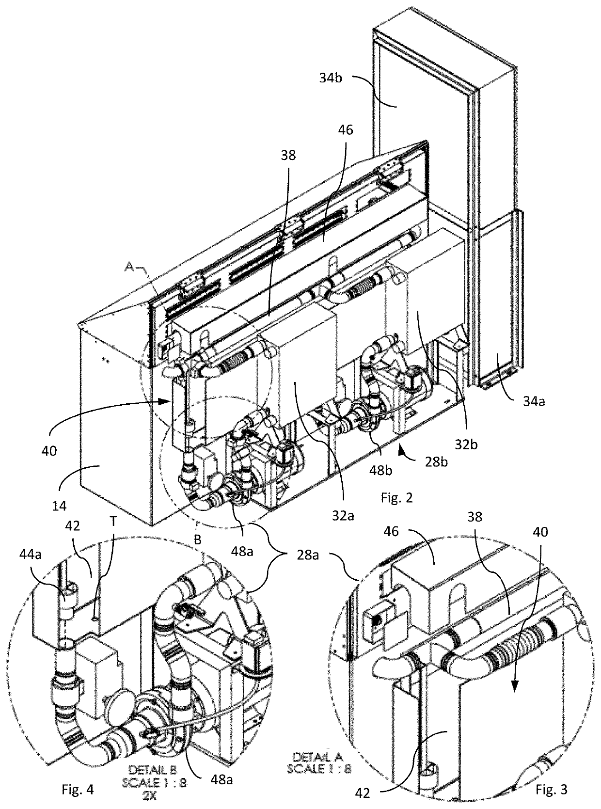
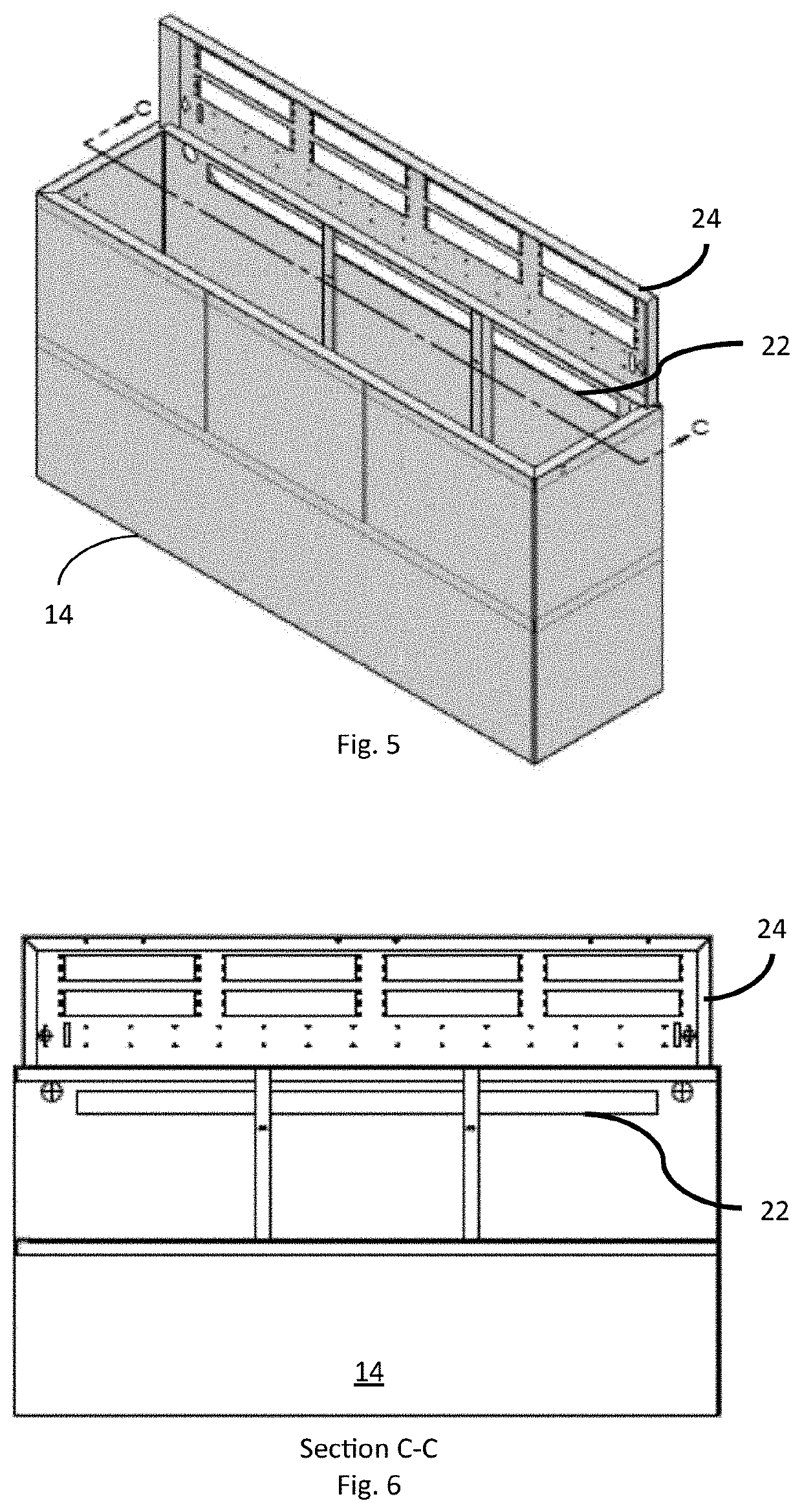
[0028]Shown in FIG. 1 (front view) and FIG. 2 (rear view) is a tank module 10 adapted for use in an appliance immersion cooling system constructed in accordance with a preferred embodiment of our invention. For convenience of reference, we have illustrated in FIG. 1 the tank facility 12 of the immersion module 10 in partial cut-away to emphasize several important internal facilities; we have shown the tank facility 12 in isolation in FIG. 5. In general, the tank facility 12 comprises: a tank 14 adapted to immerse in a dielectric fluid a plurality of electrical appliances 16, e.g., contemporary computer servers (see, e.g., FIG. 11), each in a respective appliance slot 18a distributed vertically along, and extending transverse to, a long axis of the tank 14 (see, generally, FIG. 10); an appliance rack facility 20 of convention design adapted to suspend the appliances 16 (see, e.g., FIG. 11) in respective appliance slots 18 (see, FIG. 10); a weir 22 (best seen in isolation in FIG. 5 an...


PUM


Abstract

A appliance immersion tank system comprising: a generally rectangular tank adapted to immerse in a dielectric fluid a plurality of appliances, each in a respective appliance slot distributed vertically along, and extending transverse to, the long axis of the tank; a primary circulation facility adapted to circulate the dielectric fluid through the tank; a secondary fluid circulation facility adapted to extract heat from the dielectric fluid circulating in the primary circulation facility, and to dissipate to the environment the heat so extracted; and a control facility adapted to coordinate the operation of the primary and secondary fluid circulation facilities as a function of the temperature of the dielectric fluid in the tank. A plenum, positioned adjacent the bottom of the tank, is adapted to dispense the dielectric fluid substantially uniformly upwardly through each appliance slot. A weir, integrated horizontally into a long wall of the tank, is adapted to facilitate substantially uniform recovery of the dielectric fluid flowing through each appliance slot. All active and most passive components of both the primary and secondary fluid circulation facilities, and the control facility are fully redundant, and are adapted automatically to operate in a fail-soft mode.

Description

CROSS-REFERENCE TO RELATED APPLICATIONS[0001]This application is related to the following Provisional Applications:1. Ser. No. 61 / 737,200, filed 14 Dec. 2012 (“First Parent Provisional”); and2. Ser. No. 61 / 832,211, filed 7 Jun. 2013 (“Second Parent Provisional”); and hereby claims benefit of the filing dates thereof pursuant to 37 CFR § 1.78(a)(4). (Collectively, “Parent Provisionals”). The subject matter of the Parent Provisionals, each in its entirety, is expressly incorporated herein by reference.BACKGROUND OF THE INVENTION1. Field of the Invention[0002]The present invention relates generally to electrical appliance cooling systems, and, in particular, to an improved appliance immersion cooling system and method of operation.2. Description of the Related Art[0003]In general, in the descriptions that follow, we will italicize the first occurrence of each special term of art which should be familiar to those skilled in the art of immersion cooling systems. In addition, when we firs...

Claims


Application Information

Patent Timeline
Patent Type & Authority Applications(United States)
IPC IPC(8): H05K7/20
CPCH05K7/20236H05K7/20936H05K7/20281H05K7/20272H05K7/20781
Inventor BOYD, CHRISTOPHER L.SWINDEN, KENNETH D.GARCIA, MARIO CONTITRIBOU, JOHN CHARLESTURNER, THOMAS R.KOEN, JAMES P.LAGUNA, DAVID CHRISTOPHER
Owner BOYD CHRISTOPHER L
Why Eureka
Try Eureka