Method and system for low emissivity, color neutral insulated glass units with transparent photovoltaics
a technology of insulated glass units and photovoltaics, which is applied in the field of low emissivity, color neutral insulated glass units with transparent photovoltaics, insulated, etc., can solve the problems that photovoltaic technologies have not been widely used, and achieve the effect of improving color neutrality
- Summary
- Abstract
- Description
- Claims
- Application Information
AI Technical Summary
Benefits of technology
Problems solved by technology
Method used
Image
Examples
first embodiment
[0113]According to the present invention, a photovoltaic structure that preferentially transmits red light is combined with a low emissivity structure that preferentially transmits blue light to provide a color neutral IGU.
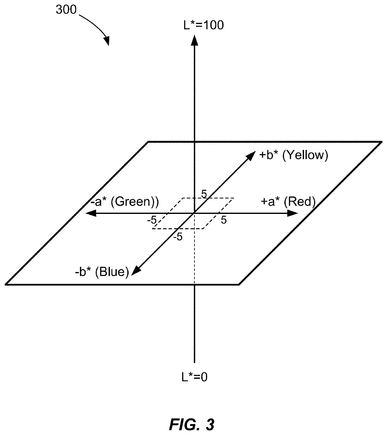
[0114]FIG. 9A is a plot illustrating simulated optical properties of a photovoltaic structure according to a first embodiment of the present invention. As illustrated in FIG. 9A, the photovoltaic structure has greater absorption in the blue portion of the spectrum than in the green or red portions of the spectrum. As a result, the photovoltaic structure transmits red wavelengths preferentially in comparison with blue wavelengths. This higher transmission at red wavelengths results in a b*value for the photovoltaic structure that is positive. For the particular photovoltaic structure having the optical properties shown in FIG. 9A, b*=12.
[0115]FIG. 9B is a plot illustrating simulated optical properties of a low emissivity structure according to the first embodiment ...
second embodiment
[0133]According to the present invention, a photovoltaic structure that preferentially transmits blue light is combined with a low emissivity coating that preferentially transmits red light to provide a color neutral IGU. In the embodiment that follows, the photovoltaic structure has higher transmission at blue wavelengths (i.e., ˜450 nm) than at green wavelengths (i.e., ˜550 nm) and red wavelengths (i.e., ˜625 nm). These spectral characteristics could result from a photovoltaic coating that absorbs in the IR, with the absorption profile tailing into red wavelengths. Accordingly, a complementary low emissivity structure with higher transmission at red wavelengths is used in this embodiment to provide an IGU that is color neutral with respect to the colors of the photovoltaic structure and the low emissivity structure.
[0134]FIG. 11A is a plot illustrating simulated optical properties of a photovoltaic structure according to a second embodiment of the present invention. As illustrated...
third embodiment
[0142]According to the present invention, a photovoltaic structure that preferentially transmits blue and red light is combined with a low emissivity coating that preferentially transmits green light to provide a color neutral IGU. In this embodiment, the photovoltaic structure is characterized by some absorption centered in the visible wavelength range, resulting in preferential transmission of red and blue wavelengths. This behavior could be associated with introduction of a visible absorber in the photovoltaic coating or an IR absorber that also includes an absorption feature in the visible portion of the optical spectrum. Accordingly, a complementary low emissivity structure with higher transmission at green wavelengths is used in this embodiment to provide an IGU that is color neutral with respect to the colors of the photovoltaic structure and the low emissivity structure.
[0143]FIG. 12A is a plot illustrating simulated optical properties of a photovoltaic structure according t...
PUM
 Abstract
Description
Claims
Application Information
 - R&D
- Intellectual Property
- Life Sciences
- Materials
- Tech Scout
- Unparalleled Data Quality
- Higher Quality Content
- 60% Fewer Hallucinations
Browse by: Latest US Patents, China's latest patents, Technical Efficacy Thesaurus, Application Domain, Technology Topic, Popular Technical Reports.
© 2025 PatSnap. All rights reserved.Legal|Privacy policy|Modern Slavery Act Transparency Statement|Sitemap|About US| Contact US: help@patsnap.com


