Electrochromic device having a self-cleaning hydrophilic coating with a controlled surface morphology

a technology of hydrophilic coating and electrochromic coating, which is applied in the direction of mirrors, instruments, vehicle components, etc., can solve the problems of oil, grease, and other contaminants that can also fill the pores of the siosub>2 /sub>layer, and achieve enhanced color neutrality, enhanced reflectance characteristics, and reduced manufacturing costs

Inactive Publication Date: 2005-12-29
GENTEX CORP
View PDF51 Cites 23 Cited by
  • Summary
  • Abstract
  • Description
  • Claims
  • Application Information

AI Technical Summary

Benefits of technology

[0015] Accordingly, it is an aspect of the present invention to solve the above-identified problems by providing a hydrophilic coating suitable for use on an electrochromic device, such as, but not limited to, an electrochromic mirror. To achieve these and other aspects and advantages, an electrochromic mirror according to the present invention comprises a variable reflectance mirror element having a reflectivity that varies in response to an applied potential so as to exhibit at least a high reflectance state and a low reflectance state, and a self-cleaning, hydrophilic coating having a controlled surface morphology. As will be discussed in greater detail infra the controlled surface morphology, among other things: (1) reduces manufacturing costs (2) enhances and / or controls reflectance characteristics; (3) enhances color neutrality and / or enhances controllability of intentional preferred coloration, such a blue hues for the European automotive industry; (4) enhances and / or controls photocatalytic properties; and (5) facilitates a broad ranges of production profiles not available heretofore—just to name a few. The electrochromic mirror according to the present invention may also exhibit a reflectance of less than 20 percent in said low reflectance state, and also preferably exhibits a C* value less than about 25 in both said high and low reflectance states so as to exhibit substantial color neutrality and is substantially haze free in both high and low reflectance states. Alternatively, the electrochromic mirror may exhibit a C* value of greater than approximately 25 in one or more of a high reflectance state and a low reflectance state if b* contributes to at least approximately 50% of the C* value, and more preferably at least approximately 75% of the C* value.

Problems solved by technology

These water beads are then either swept away by windshield wipers or are blown off the window as the vehicle moves.
However, if a hydrophobic coating is applied to the external rearview mirrors, the water beads formed on their surfaces cannot be effectively blown off since such mirrors are relatively shielded from direct airflow resulting from vehicle movement.
Further, when the water droplets evaporate, water spots are left on the mirror, which are nearly as distracting as the water droplets that left the spots.
Such a mist can be so dense that it effectively renders the mirrors virtually unusable.
One problem with such single layer coatings of SiO2 is that oil, grease, and other contaminants can also fill the pores of the SiO2 layer.
Many such contaminants, particularly hydrocarbons like oil and grease, do not readily evaporate and hence clog the pores of the SiO2 layer.
When the pores of the SiO2 layer become clogged with car wax, oil, and grease, the mirror surface becomes hydrophobic and hence the water on the mirror tends to bead leading to the problems noted above.
The hydrophilic effect of this coating, however, tends to reverse over time when the mirror is not exposed to UV radiation.
While the above hydrophilic coatings work well on conventional rearview mirrors having a chrome or silver layer on the rear surface of a glass substrate, they have not been utilized for use on variable reflectance mirrors, such as electrochromic mirrors, for several reasons.
Such a higher low-end reflectivity obviously significantly reduces the range of variable reflectance the mirror exhibits and thus reduces the effectiveness of the mirror in reducing annoying glare from the headlights of rearward vehicles.
Another reason that the prior hydrophilic coatings have not been utilized for use on many electro-optic elements even in applications where a higher low-end reflectance may be acceptable or even desirable is that they impart significant coloration problems.
However, if used on an electrochromic element, such a hydrophilic coating would impart a very objectionable coloration, which is made worse by other components in the electrochromic element that can also introduce color.
Another reason that prior art coatings have not been utilized for use on many electro-optic elements is haze.
In an electrochromic mirror in the low reflectance state, however, most of the light is reflected off of the first surface and the ratio of scattered light to total reflected light is much higher, creating a foggy or unclear reflected image.
Due to the problems associated with providing a hydrophilic coating made of TiO2 on an electrochromic mirror, manufacturers of such mirrors have opted to not use such hydrophilic coatings.
As a result, electrochromic mirrors suffer from the above-noted adverse consequences caused by water drops and mist.

Method used


Image

  • Electrochromic device having a self-cleaning hydrophilic coating with a controlled surface morphology
  • Electrochromic device having a self-cleaning hydrophilic coating with a controlled surface morphology
  • Electrochromic device having a self-cleaning hydrophilic coating with a controlled surface morphology

Examples


example 1

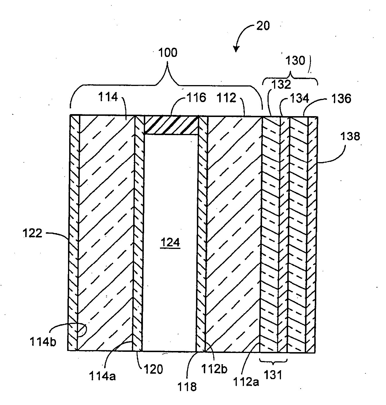
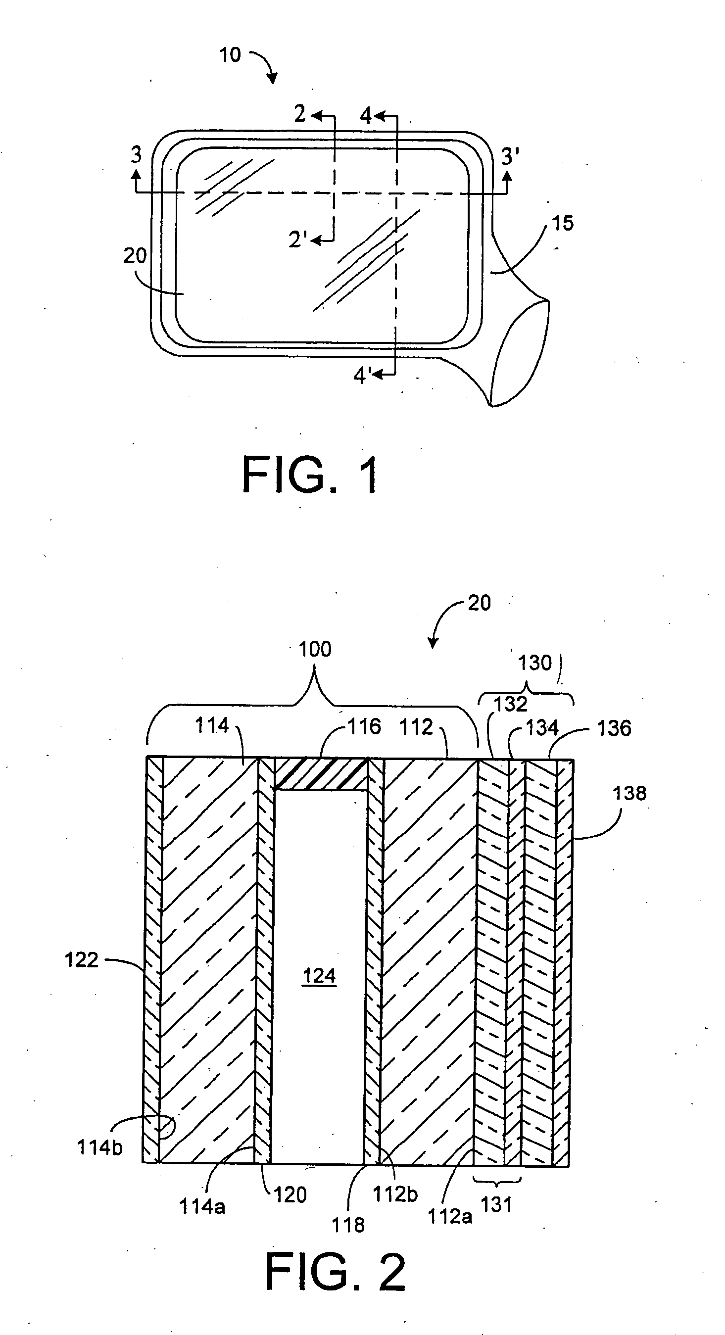
[0083] Two identical electrochromic mirrors were constructed having a rear element made with 2.2 mm thick glass with a layer of chrome applied to the front surface of the rear element and a layer of rhodium applied on top of the layer of chrome using vacuum deposition. Both mirrors included a front transparent element made of 1.1 mm thick glass, which was coated on its rear surface with a transparent conductive ITO coating of ½ wave optical thickness. The front surfaces of the front transparent elements were covered by a coating that included a first layer of 200 Å thick TiO2, a second layer of 250 Å thick SiO2, a third layer of 1000 Å TiO2, and a fourth layer of 500 Å thick SiO2. For each mirror, an epoxy seal was laid about the perimeter of the two coated glass substrates except for a small port used to vacuum fill the cell with electrochromic solution. The seal had a thickness of about 137 microns maintained by glass spacer beads. The elements were filled with an electrochromic s...

example 2

[0086] An electrochromic mirror was constructed in accordance with the description of Example 1 with the exception that a different first surface coating stack was deposited. The first surface stack consisted of a first layer of ITO having a thickness of approximately 700 Å, a second layer of TiO2 having thickness of 2400 Å, and a third layer of SiO2 having a thickness of approximately 100 Å. The physical thickness of the ITO layer corresponds to approximately ¼ wave optical thickness at 500 nm and the physical thickness of the TiO2 layer corresponds to approximately 1 wave optical thickness at 550 nm. The proportion of anatase titania to rutile titania in the TiO2 layer was determined to be about 89 percent anatase form and 11 percent rutile form from X-ray diffraction analysis of a similar piece taken from glass run in the same timeframe under similar coating parameters.

[0087] In the high reflectance state, the electrochromic mirror had the following averaged values: L*=80.37, a*...

example 3

[0088] An electrochromic mirror was modeled using commercially available thin film modeling software. In this example, the modeling software was FILMSTAR available from FTG Software Associates, Princeton, N.J. the electrochromic mirror that was modeled had the same constructions as in Examples 1 and 2 above except for the construction of the optical coating applied to the front surface of the mirror. Additionally, the mirror was only modeled in a dark state assuming the completely absorbing electrochromic fluid of index 1.43. The optical coating stack consisted of a first layer of SnO2 having a thickness of 720 Å and a refractive index of 1.90 at 550 nm, a second layer of dense TiO2 having a thickness of 1552 Å and a refractive index of about 2.43 at 550 nm, a third layer of a material with an index of about 2.31 at 550 nm and a wavelength-dependent refractive index similar to TiO2 applied at a thickness of 538 Å, and a fourth layer of SiO2 having a refractive index of 1.46 at 550 n...


PUM


Abstract

A variable reflectance rearview mirror for a vehicle, comprising: (a) a variable reflectance mirror element having a reflectivity that varies in response to an applied potential so as to exhibit at least a high reflectance state and a low reflectance state; (b) a self-cleaning, hydrophilic coating applied to a front surface of said mirror element having a controlled surface morphology.

Description

CROSS-REFERENCE TO RELATED APPLICATIONS [0001] This application is a continuation-in-part of U.S. application Ser. No. 10 / 976,940, filed Oct. 29, 2004, entitled “ELECTROCHROMIC DEVICE HAVING A SELF-CLEANING HYDROPHILIC COATING WITH AN ACID RESISTANT UNDER LAYER” which claims the benefit of U.S. Provisional Application Ser. No. 60 / 515,588, filed Oct. 30, 2003, entitled “ELECTROCHROMIC DEVICE HAVING A SELF-CLEANING HYDROPHILIC COATING WITH AN ACID RESISTANT UNDER LAYER” which are hereby incorporated herein by reference in their entirety, including all references cited therein. This application also relates to U.S. application Ser. No. 09 / 602,919, filed Jun. 23, 2000, entitled “AN ELECTRO-OPTIC DEVICE HAVING A SELF-CLEANING HYDROPHILIC COATING” as well as U.S. Pat. No. 6,193,378, filed Nov. 5, 1999, entitled “ELECTROCHROMIC DEVICE HAVING A SELF-CLEANING HYDROPHILIC COATING” both of which are hereby incorporated herein by reference in their entirety, including all references cited there...

Claims


Application Information

Patent Timeline
Patent Type & Authority Applications(United States)
IPC IPC(8): G02B1/00G02B5/08G02B17/00
CPCB60R1/088B60R1/0602
Inventor TONAR, WILLIAM L.ANDERSON, JOHN S.FORGETTE, JEFFREY A.KAR, KEVIN B.DOZEMAN, GARY J.NEUMAN, GEORGE A.FROSTENSON, BRETT R.
Owner GENTEX CORP
Why Eureka
Try Eureka