Panoramic look-around view generation method, in-vehicle device and in-vehicle system

a technology of in-vehicle devices and look-around views, applied in the field of machine vision, to achieve the effect of accurate analysis and judgment, and improved driving safety

Pending Publication Date: 2022-04-07
BLACK SESAME TECH INC
View PDF26 Cites 4 Cited by
  • Summary
  • Abstract
  • Description
  • Claims
  • Application Information

AI Technical Summary

Benefits of technology

[0007]generating a look-around view associated with time by transforming and mosaicking images acquired from the plurality of cameras, using the look-around view generated at current time as the look-around view at current time, and saving the look-around view at current time;
[0011]According to the panoramic look-around view generation method described above, the ORB algorithm is used to respectively extract the characteristic points of the look-around view at previous time and the look-around view at current time, and then the steering wheel angle information and the vehicle speed information are used to calculate a position of a characteristic point of the look-around view at previous time in the look-around view at current time according to a vehicle motion model, so that a characteristic point located near the position is selected from the characteristic points of the look-around view at current time to be matched with the characteristic point of the look-around view at previous time. In this way, the calculation amount of characteristic point matching can be effectively reduced, and the accuracy of characteristic point matching is improved. After that, the affine transformation matrix between the look-around view at previous time and the look-around view at current time is calculated, and the affine transformation matrix is used to realize a panoramic look-around view, so that the display blind area of the underbody region in the look-around view can be eliminated. Therefore, the driver and passenger can know the road condition of the underbody region in real time, accurately analyze and judge the position and condition of the vehicle during driving, thereby improving the driving safety.
[0028]In the in-vehicle device, the image processing unit is further configured to obtain a first transformation matrix of image coordinate systems from the previous time to the current time according to the vehicle motion model by using the steering wheel angle information and the vehicle speed information; the image processing unit is further configured to determine a position of a characteristic point of the look-around view at previous time in the look-around view at current time using the first transformation matrix, so that a characteristic point located near the position is selected in the look-around view at current time to be matched with the characteristic point of the look-around view at previous time. The calculation amount of characteristic point matching can be effectively reduced, and the accuracy of characteristic point matching is improved. After that, the affine transformation matrix between the look-around view at previous time and the look-around view at current: time is calculated, and the affine transformation matrix is used to realize a panoramic look-around view, so that the display blind area of the underbody region in the top view of the vehicle body can be eliminated, the driver and passenger can know the road condition of the underbody region in real time, accurately analyze and judge the position and condition of the vehicle during driving, thereby improving the driving safety.
[0034]In the in-vehicle system, the cameras capture the image information, and then the in-vehicle device acquires the image and vehicle motion information, processes and transforms the image and the vehicle motion information to generate a panoramic look-around view. Then the panoramic look-around view is displayed through a display unit, so that the panoramic look-around view including the underbody region can be displayed in time, the road condition of the vehicle underbody region can be known in real time by drivers and passengers conveniently. The position and the condition of the vehicle during driving can be accurately analyzed and judged, and the driving safety is improved.

Problems solved by technology

However, such a panoramic look-around system cannot capture the image of the underbody region, which results in that the underbody region cannot be displayed in the panoramic look-around view, forming a blind area for displaying the underbody region, affecting the analysis of the road conditions in the underbody region and the position judgment during driving by drivers and passengers of the vehicle.

Method used


Image

  • Panoramic look-around view generation method, in-vehicle device and in-vehicle system
  • Panoramic look-around view generation method, in-vehicle device and in-vehicle system
  • Panoramic look-around view generation method, in-vehicle device and in-vehicle system

Examples


Embodiment Construction

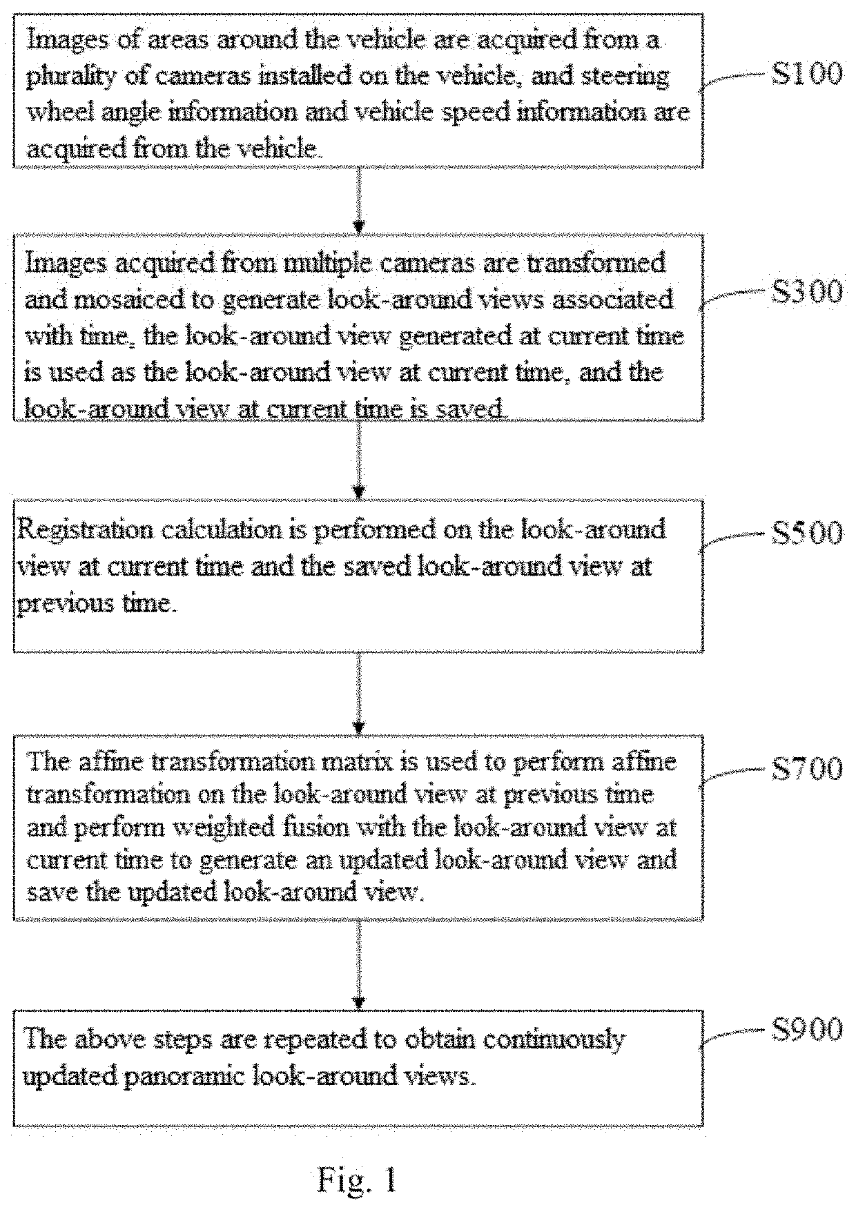
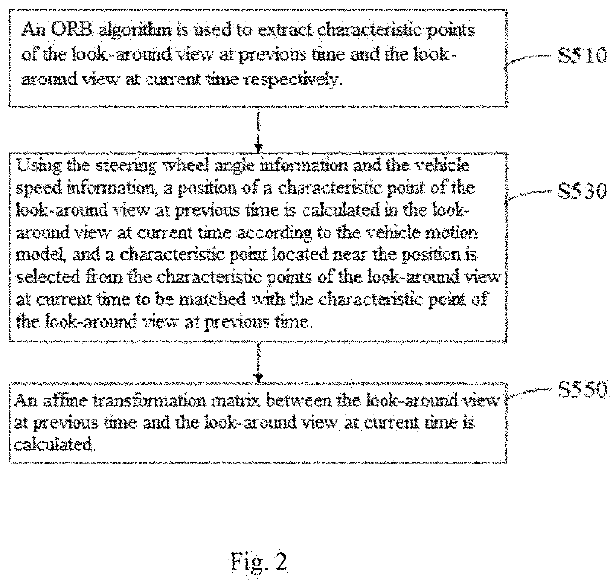
[0048]Please refer to FIGS. 1 to 4, FIG. 1 is a flowchart of a panoramic look-around view generation method according to an embodiment of the present application. FIG. 2 is a sub-flowchart of registration calculation of the panoramic look-around view generation method according to the embodiment of FIG. 1. FIG. 3 is a schematic view showing effects of a panoramic look-around view generation method according to an embodiment of the present application. FIGS. 4A and 4B are comparative schematic views of a look-around view at previous time and a look-around view at current time of the panoramic look-around view generation method according to an embodiment of the present application.

[0049]As shown in FIG. 1, the panoramic look-around view generation method includes the following steps.[0050]S100: images of areas around the vehicle are acquired from a plurality of cameras installed on the vehicle, and steering wheel angle information and vehicle speed information are acquired from the ve...


PUM


Abstract

The current disclosure relates to a panoramic look-around view generation method, an in-vehicle device and an in-vehicle system. The method comprises the following steps of: acquiring images of areas around a vehicle, steering wheel angle information and vehicle speed information; transforming and mosaicking the images to generate a time-related look-around view, and using an ORB algorithm to extract characteristic points; using steering wheel angle information and vehicle speed information to calculate a positron of a characteristic point of the look-around view at previous time in the look-around view at current time according to a vehicle motion model, and selecting a characteristic point located near the position in the look-around view at current time to be matched with the characteristic point of the look-around view at previous time; calculating an affine transformation matrix and performing affine transformation, and performing weighted fusion with the look-around view at current time and storing it; repeating the above steps to obtain a continuously updated panoramic look-around view, The method, the device and the system can eliminate blind area in the underbody region, realize a panoramic perspective view, and have fast calculation and high accuracy.

Description

BACKGROUND(1) Technical Field[0001]The current disclosure relates to the field of machine vision, in particular to a panoramic look-around view generation method, an in-vehicle device and an in-vehicle system.(2) Background[0002]With rapid development of image and computer vision technology, more and more vehicles begin to install panoramic look-around systems. Existing panoramic look-around systems generally include imaging devices and image processing units. The imaging device includes a plurality of cameras capable of covering all view field range around the vehicle, for example, fisheye cameras with wide view field range respectively installed at the front and rear of the vehicle, and at the left and right rearview mirrors, etc. These cameras image the surrounding environment of the vehicle and transmit the acquired images to the image processing unit. The image processing unit associates the received image with time, and processes the images from multiple cameras at the same ti...

Claims


Application Information

Patent Timeline
Patent Type & Authority Applications(United States)
IPC IPC(8): H04N5/232G06T3/40G06T7/33G06T3/00B60R11/04B60R11/02B60R1/00
CPCH04N5/23238G06T3/4038G06T7/337G06T3/0006B60R11/04B60R2300/303B60R1/00G06T2207/30252B60R2300/105B60R2300/302B60R11/0229G06T7/33G06T2207/10016B60R2300/60B60R2300/607B60R2300/30B60R1/27H04N23/698H04N23/90
Inventor LI, WENXUE
Owner BLACK SESAME TECH INC
Why Eureka
Try Eureka