
Method and system for controlling the operation of a csp receiver

a technology of csp receiver and operation method, which is applied in solar heat systems, solar heat simulation/prediction, lighting and heating apparatus, etc., can solve the problems of significant undesirable outlet temperature over- and undershoot, fundamental control of flow rate to regulate output temperature, and relatively unstable closed loop control of flow ra

Pending Publication Date: 2022-04-21
VAST SOLAR PTY
View PDF0 Cites 0 Cited by
  • Summary
  • Abstract
  • Description
  • Claims
  • Application Information

AI Technical Summary

Benefits of technology

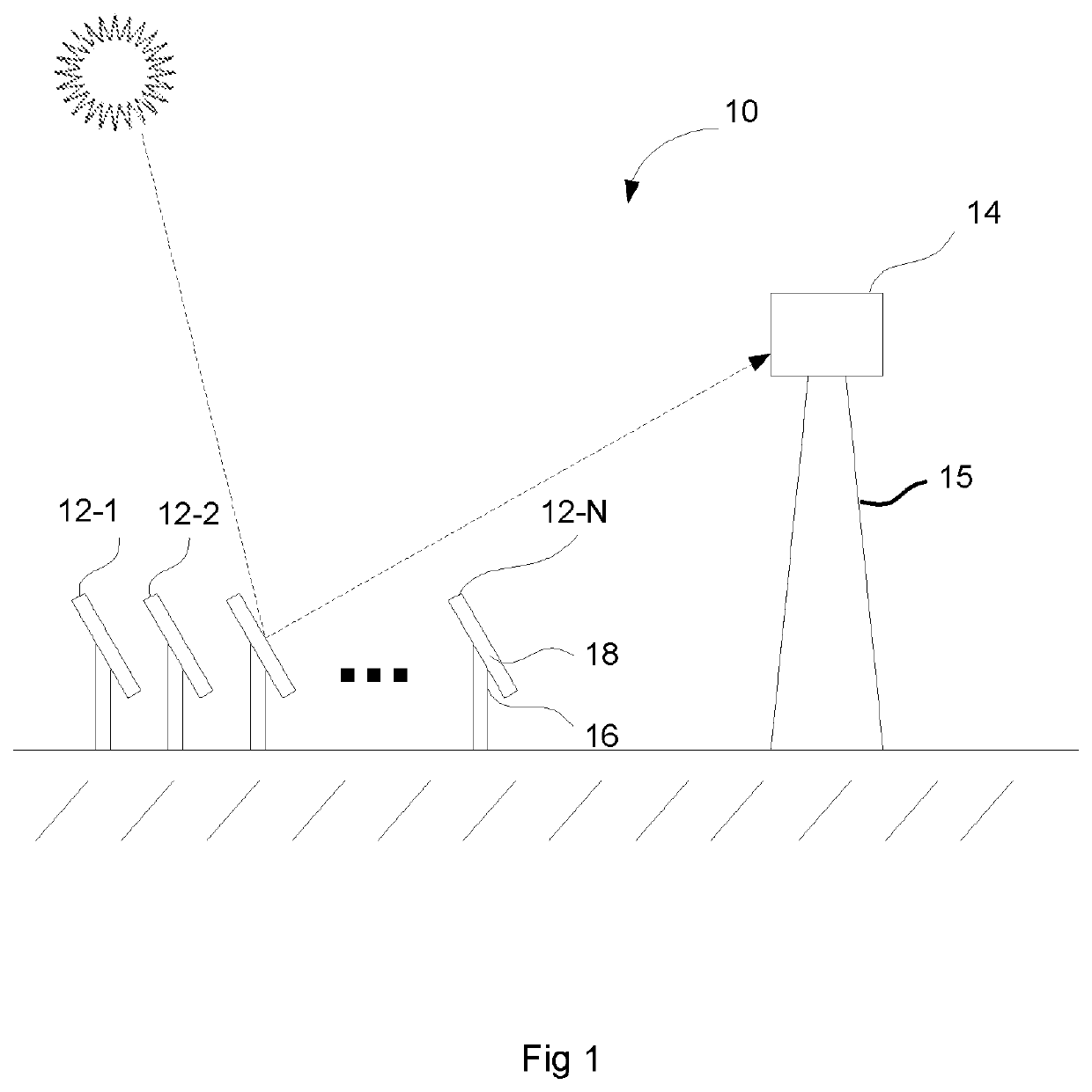
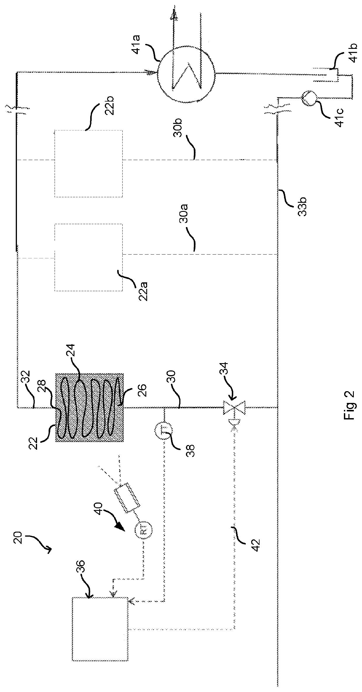
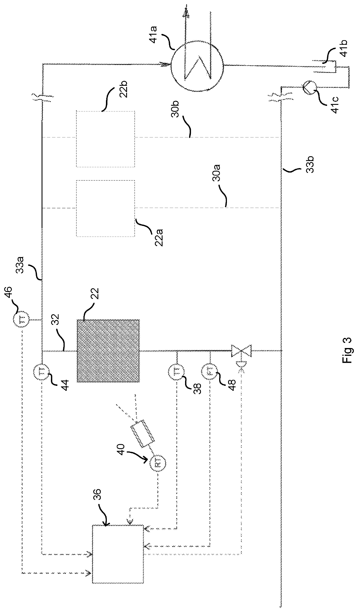
The patent describes a concentrated solar energy collection system that uses a plurality of heliostats to focus sunlight onto a solar receiver with tubes that carry a heat transfer fluid. The system includes a controller that regulates the flow of heat transfer fluid through the tubes by controlling the valve arrangement. The system also includes sensors to measure the solar radiation and the temperature of the heat transfer fluid. The system can be used in a concentrated solar energy installation to produce heat for use in a steam turbine. The technical effects of the invention include efficient solar energy collection and utilization for generating energy in a cost-effective and environmentally friendly manner.

Problems solved by technology

The combination of very rapid changes in heat input, both voluntary and involuntary, with a requirement for a stable output temperature makes the control of flow rate to regulate output temperature fundamentally difficult.
Closed loop control of the flow rate using feedback from the outlet temperature is relatively unstable as the effect of receiver heat input variations on outlet temperature has a significant time delay, and results in significant undesirable outlet temperature over- and under-shoots.
Closed loop control can be improved by using thermal imagery to measure the temperatures across the receiver, however while this reduces the time delay in the feedback, the control remains relatively unstable.

Method used


Image

  • Method and system for controlling the operation of a csp receiver
  • Method and system for controlling the operation of a csp receiver
  • Method and system for controlling the operation of a csp receiver

Examples


Embodiment Construction

[0029]Control stability can be improved by using measurements of solar radiation incident on the solar field as inputs to the control system. The solar radiation measurements may be included either through modelling or empirical measurement of the effect of the solar radiation on HTF temperature to implement feed forward control loops or other non-linear predictive controls. Solar radiation measurement can thus be used to forecast the future outlet temperature for different control valve settings. In order to accurately measure solar radiation on the field many solar radiation or flux detectors would need to be mounted throughout the solar field. This could be done on each heliostat or on / centered on small clusters of heliostats. This is resource intensive as well as not always being representative of the radiation falling on the receiver when all the heliostat mirrors are not focussed on the receiver precisely or at all.

[0030]A further HTF control complication relates to the achiev...


PUM


Abstract

A concentrated solar energy collection system includes an array of heliostats and a solar receiver that further includes a plurality of tubes having at least one inlet and at least one outlet for carrying a heat transfer fluid (HTF). A flow control arrangement is provided for controlling the flow of HTF through the tubes. This includes at least one radiation sensor such as a pyranometer for sensing values representative of the aggregate solar radiation falling on the solar receiver via the heliostats. At least one temperature sensor measures input temperature of the HTF at or near the inlet. A controller coupled to the radiation and temperature sensors regulates the outlet temperature of the HTF by controlling the flow of HTF through the tubes via the flow control arrangement. A pressure differential sensor arrangement measures pressure differential across the flow control arrangement, providing an input to the controller.

Description

FIELD OF THE INVENTION[0001]The present disclosure relates to a method and system for controlling the operation of a CSP (concentrated solar power) receiver, as well as to a CSP installation incorporating such a system.BACKGROUND OF THE INVENTION[0002]In one form of tower-based CSP, the use of the sun's reflections as a heat source is applied to heating a heat transfer fluid (HTF) by focusing the sun onto a tower-based receiver using an array of sun-tracking heliostat mirrors. The HTF is passed through the receiver and heated to a target outlet temperature. It is desirable to minimise variations in the outlet temperature, both for improved process control of the power block, and to reduce stress variations and improve life for those mechanical and structural components affected by the HTF temperature.[0003]As the heat input from a CSP plant relies on focusing the sun on the receiver, it can vary almost instantly from full to zero power. This can occur either involuntarily, with the ...

Claims


Application Information

Patent Timeline
IPC IPC(8): F24S50/40F24S10/70F24S20/20F24S23/77F24S80/20
CPCF24S50/40F24S10/70F24S80/20F24S23/77F24S20/20Y02E10/44F24S2201/00
Inventor CURTIS, ALLANDREWES, KURT FRIEDRICHBLINCO, NICOLE ANN
Owner VAST SOLAR PTY
Learn More