
Display device

a display device and display technology, applied in the direction of identification means, electrical apparatus casings/cabinets/drawers, cooling/ventilation/heating modifications, etc., can solve the problems of affecting heat dissipation efficiency, inevitably mixing with water vapor and dust, affecting their lifespan, etc., to improve heat dissipation efficiency, reduce resistance, prevent excessive components

Active Publication Date: 2022-04-21
SHENZHEN CHINA STAR OPTOELECTRONICS SEMICON DISPLAY TECH CO LTD
View PDF0 Cites 0 Cited by
  • Summary
  • Abstract
  • Description
  • Claims
  • Application Information

AI Technical Summary

Benefits of technology

The present patent aims to solve the issue of dust, water vapor, and other substances easily entering the heat dissipation system of a display device, which affects its service life. The display device of the present invention has a separate air tunnel for heat dissipation with functional devices on both sides, preventing excessive components from blocking airflow and improving heat dissipation efficiency and service life. Additionally, the separate air tunnel isolates the power plate and core plate from outdoor dust and water vapor, ensuring their operating stability and service life extension.

Problems solved by technology

On the one hand, this affects airflow of wind in the heat dissipation channel because the wind is blocked by unevenness of the power plate and the core plate, thereby affecting heat dissipation efficiency.
Also, since the wind comes from outside, it inevitably mixes with water vapor and dust.
Although filtered by a filtering system, some tiny dust and water vapor inevitably enter the air tunnel, fall into the power plate and the core plate, and affect their lifespan, and even directly causing short circuiting between the power plate and the core plate.

Method used


Image

  • Display device

Examples


embodiment 1

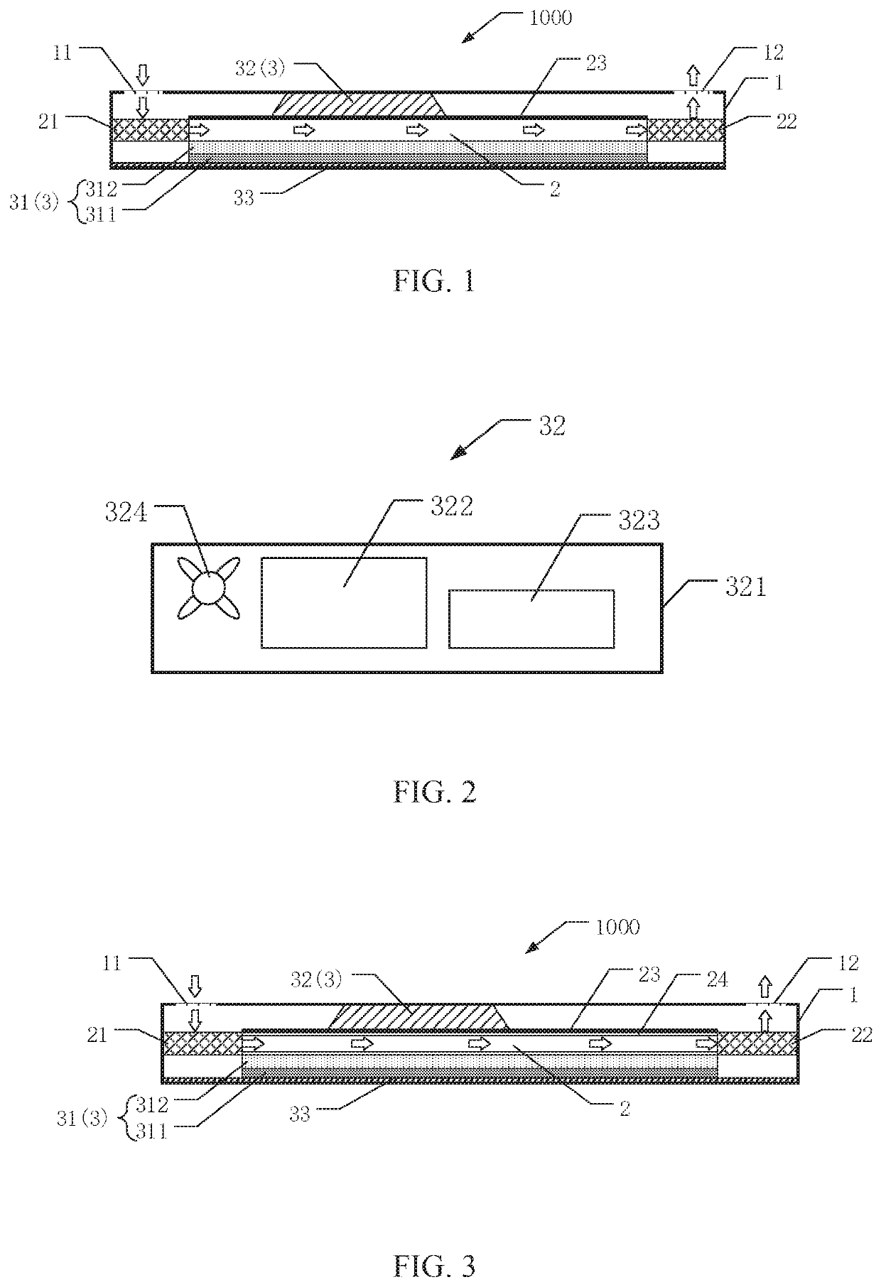
[0025]An embodiment of the present disclosure provides a display device 1000. As shown in FIG. 1, the display device 1000 includes a housing 1, an air tunnel 2, a blower fan 21, an ejector fan 22, and a functional device 3. The functional device 3 includes a display screen 31 and a motor device 32.

[0026]The display screen 31 is disposed in the housing 1 and has a display surface faces outward of the housing 1. The display screen 31 includes a liquid crystal display panel 311 and a backlight module 312. The liquid crystal display panel 311 is disposed on a side of the display screen 31 close to the display surface thereof, and the backlight module 312 is disposed on the liquid crystal display panel 311.

[0027]The liquid crystal display panel 311 includes devices such as an array substrate, a color film substrate, and a liquid crystal housing. There are liquid crystals in the liquid crystal housing. The liquid crystals are a special substance between solid and liquid. They are organic ...

embodiment 2

[0036]A display device 1000 is provided in an embodiment of the present disclosure. As shown in FIG. 3, the layered structure of the display device 1000 in this embodiment of the present disclosure is similar to the layered structure in embodiment 1, but in this embodiment, an inner wall of the air tunnel 2 is provided with a heat dissipation layer 24, that is, a side of the partition plate 23 toward the air tunnel 2 and a side of the backlight module 312 toward the air tunnel 2 are covered with the heat dissipation layer 24. The heat dissipation layer 24 may be a material with excellent thermal conductivity such as a heat dissipation paint and graphene, and is used to improve the heat dissipation efficiency of the display device 1000.

[0037]Embodiment 1 and embodiment 2 of the present disclosure only include one layer of the partition plate 23, but in other embodiments of the present disclosure, there may be two layers of the partition plates 23, which are respectively provided betw...


PUM

PropertyMeasurementUnit
surface roughnessaaaaaaaaaa
brightnessaaaaaaaaaa
temperatureaaaaaaaaaa

Abstract

The present disclosure provides a display device, including a housing, an air tunnel, and a functional device. The housing includes an air inlet and an air outlet, wherein the air inlet and the air outlet are disposed on two sides of the housing opposite to each other. The air tunnel is disposed in the housing and extends from the air inlet to the air outlet; and the functional device is disposed in the housing and located outside the air tunnel.

Description

FIELD OF INVENTION[0001]The present disclosure relates to the field of display technologies, and more particularly, to a display device.BACKGROUND OF INVENTION[0002]For high-brightness liquid crystal displays for outdoor applications, on the one hand, due to higher ambient temperature outdoors (especially in summer), backlight is affected by the ambient temperature and has a higher temperature; on the other hand, because the backlight itself emits more heat and light, an independent air tunnel design is adopted to enhance heat dissipation of the backlight, so that the heat can be dissipated as much as possible to prevent normal function of the display from being affected by overheating backlight.[0003]Generally, a fan, a heat dissipating backlight, a power plate, and a core plate are disposed in a heat dissipation channel of a heat dissipation system. On the one hand, this affects airflow of wind in the heat dissipation channel because the wind is blocked by unevenness of the power ...

Claims


Application Information

Patent Timeline
Patent Type & Authority Applications(United States)
IPC IPC(8): G02F1/1333H05K7/20
CPCG02F1/133385H05K7/20972G02F1/133382G09F9/00H05K5/0213H05K7/20954
Inventor SHI, ZHENHUAYIN, TAIYONGYI, CENLUO, CONGTANG, SHAOTUO
Owner SHENZHEN CHINA STAR OPTOELECTRONICS SEMICON DISPLAY TECH CO LTD
Learn More