Blood pump

a technology of blood pump and torque generator, which is applied in the direction of blood pump, circulatory assistance device, suction device, etc., can solve the problem of loss of magnetic flow for torque generation

Pending Publication Date: 2022-05-12
ABIOMED EURO
View PDF0 Cites 0 Cited by
  • Summary
  • Abstract
  • Description
  • Claims
  • Application Information

AI Technical Summary

Benefits of technology

The invention is about a new design of pumps that use magnets to generate torque. The design includes triangular-shaped posts that are packed around the axis of rotation, which helps to increase the ratio of torque to axial forces between the drive unit and the impeller. The design also reduces magnetic losses between neighboring posts, which results in higher efficiency. Overall, the new design improves the performance and space utilization of pumps.

Problems solved by technology

Such magnetic flow is lost for the generation of torque.

Method used


Image

  • Blood pump
  • Blood pump
  • Blood pump

Examples


Embodiment Construction

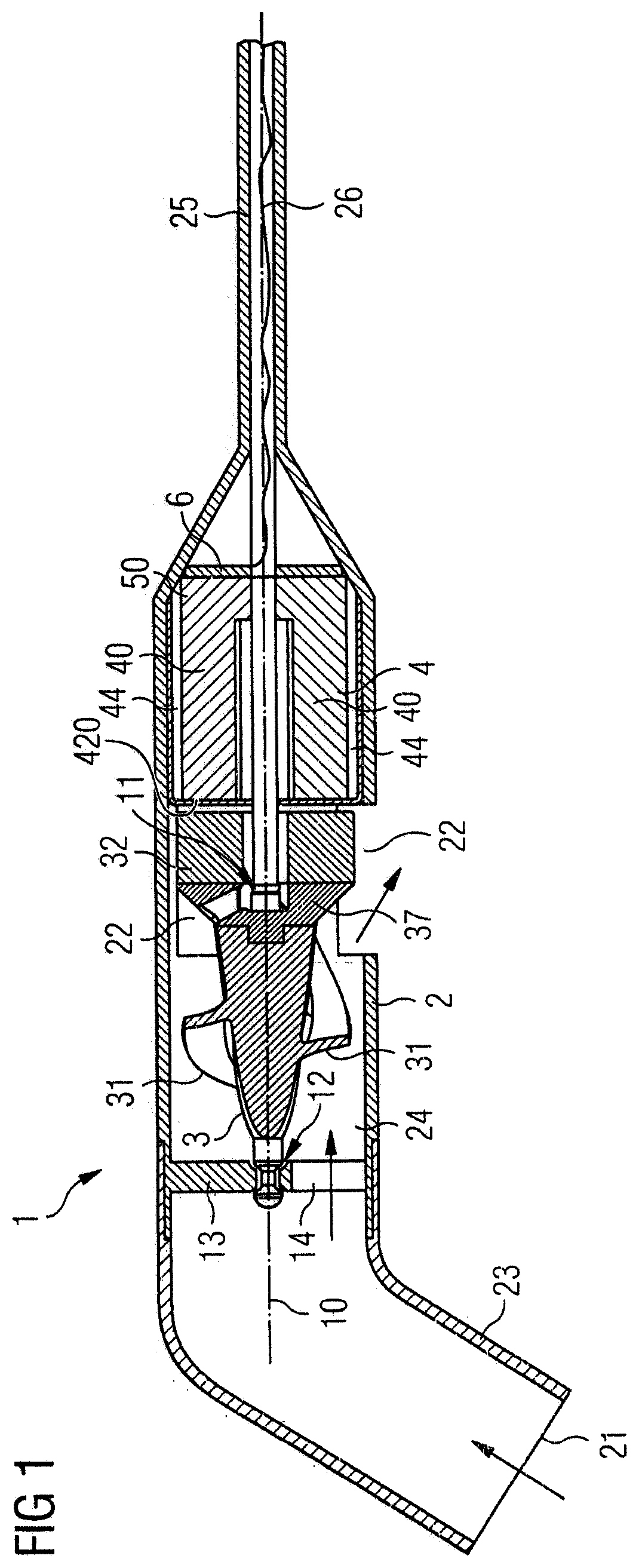
[0045]Referring to FIG. 1, a cross-sectional view of a blood pump 1 is illustrated. The blood pump 1 comprises a pump casing 2 with a blood flow inlet 21 and a blood flow outlet 22. The blood pump 1 is designed as an intravascular pump, also called a catheter pump, and is deployed into a patient's blood vessel by means of a catheter 25. The blood flow inlet 21 is at the end of a flexible cannula 23 which may be placed through a heart valve, such as the aortic valve, during use. The blood flow outlet 22 is located in a side surface of the pump casing 2 and may be placed in a heart vessel, such as the aorta. 345 The blood pump 1 is electrically connected with an electric line 26 extending through the catheter 25 for supplying the blood pump 1 with electric power in order to drive the pump 1 by means of a drive unit 4, as explained in more detail below.

[0046]If the blood pump 1 is intended to be used in long term applications, i.e. in situations in which the blood pump 1 is implanted i...


PUM


Abstract

This invention concerns an intravascular blood pump for percutaneous insertion into a patient's blood vessel. The blood pump comprises a pump casing having a blood flow inlet and a blood flow outlet, and an impeller arranged in said pump casing so as to be rotatable about an axis of rotation. The impeller has blades sized and shaped for conveying blood from the blood flow inlet to the blood flow outlet. The blood pump comprises a drive unit for rotating the impeller, the drive unit comprising a plurality of posts arranged about the axis of rotation. Each of the posts has a longitudinal axis and an impeller-side end pointing towards the impeller. A coil winding is disposed around each of the posts and has an impeller-side end pointing towards the impeller. The coil windings are controllable so as to create a rotating magnetic field, wherein the impeller comprises a magnetic structure arranged to interact with the rotating magnetic field so as to cause rotation of the impeller. The posts do not extend with their impeller-side ends radially over the impeller-side ends of the coil winding disposed around the respective posts, wherein the term radially relates to the longitudinal axis of the posts.

Description

[0001]This invention relates to a blood pump, in particular an intravascular blood pump for percutaneous insertion into a patient's blood vessel, to support a blood flow in a patient's blood vessel. The blood pump has an improved drive unit.BACKGROUND OF INVENTION[0002]Blood pumps of different types are known, such as axial blood pumps, centrifugal (i.e. radial) blood pumps or mixed-type blood pumps, where the blood flow is caused by both axial and radial forces. Intravascular blood pumps are inserted into a patient's vessel such as the aorta by means of a catheter. A blood pump typically comprises a pump casing having a blood flow inlet and a blood flow outlet connected by a passage. In order to cause a blood flow along the passage from the blood flow inlet to the blood flow outlet, an impeller or rotor is rotatably supported within the pump casing, with the impeller being provided with blades for conveying blood.[0003]Blood pumps are typically driven by a drive unit, which can be ...

Claims


Application Information

Patent Timeline
IPC IPC(8): A61M60/806A61M60/135A61M60/216A61M60/422A61M60/81A61M60/865A61M60/825A61M60/13A61M60/139A61M60/508A61M60/804
CPCA61M60/806A61M60/135A61M60/216A61M60/825A61M60/81A61M60/865A61M60/422A61M60/13A61M60/237A61M60/221A61M60/139A61M60/508A61M60/804
Inventor GRAUWINKEL, MARIUSKERKHOFFS, WOLFGANG
Owner ABIOMED EURO
Why Eureka
Try Eureka