Electromagnetic device and system for pumping, circulating or transferring non-ferrous molten metal

a technology of non-ferrous molten metal and electric motor, which is applied in the direction of molten metal supply equipment, electrical apparatus, dynamo-electric machines, etc., can solve the problems of difficult access to an inductor for maintenance, costly downtime of the whole furnace or melting equipment, etc., to improve the homogeneity of the flow, improve the efficiency of the operation, and the physical characteristics are weaker

Pending Publication Date: 2022-05-12
EMP TECH
View PDF0 Cites 0 Cited by
  • Summary
  • Abstract
  • Description
  • Claims
  • Application Information

AI Technical Summary

Benefits of technology

[0046]Unlike existing electromagnetic pumps, the inductor assembly is not physically coupled to the duct or to insulation surrounding the duct. As a result, the inductor assembly can be removed without removing the duct or insulation surrounding the duct, making maintenance quicker and more straightforward.
[0047]The insulating layers ensure that the outer surface of the electromagnetic device is safe to touch. They also ensure that the inductor assemblies are not adversely affected by the heat from the molten metal, for example, preventing coolant from boiling which might lead to damaging vapour expansion.
[0048]An insulation layer may be interposed between the first inductor assembly and the duct. An insulation layer may be interposed between the second inductor assembly and the duct. The insulation layer may comprise a thermally insulating ceramic. Each insulation layer may comprise two sublayers made from different materials. For example an inner layer closest to the duct may comprise a less insulating

Problems solved by technology

This makes accessing an inductor for maintenance difficult.
If one of the inductor coils develops a fault and needs replacing, the entire el

Method used


Image

  • Electromagnetic device and system for pumping, circulating or transferring non-ferrous molten metal
  • Electromagnetic device and system for pumping, circulating or transferring non-ferrous molten metal
  • Electromagnetic device and system for pumping, circulating or transferring non-ferrous molten metal

Examples


Embodiment Construction

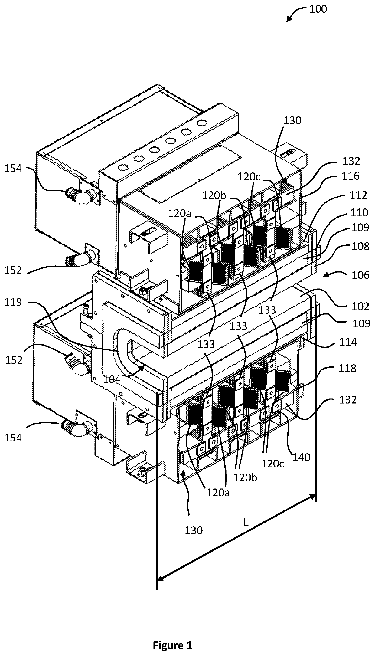
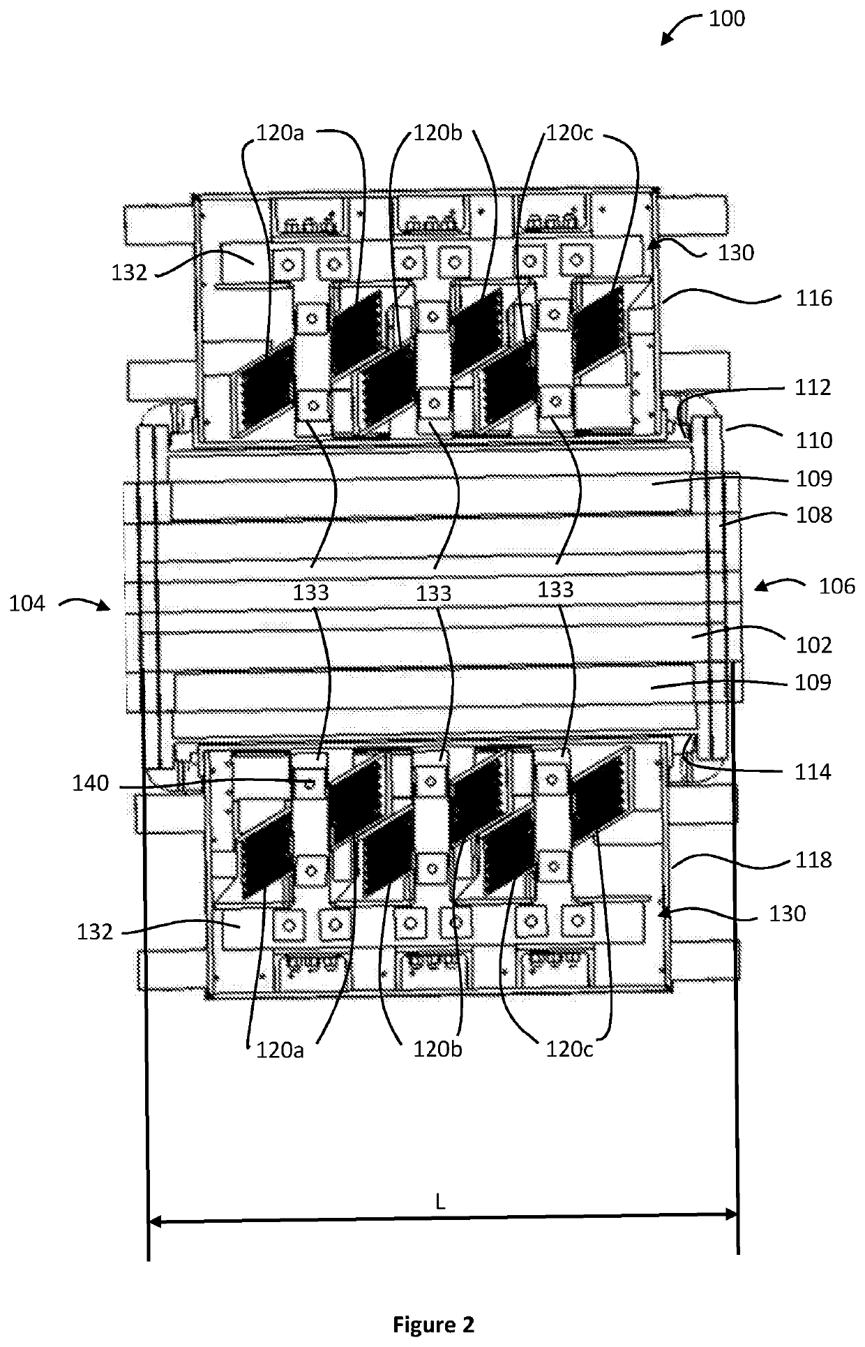
[0065]FIGS. 1 and 2 illustrate a cross-section through the centre of an electromagnetic device 100 for pumping, circulating or transferring non-ferrous molten metal. The electromagnetic device 100 has a duct 102 formed of a refractory material 108 such as silicon carbide, which is able to resist the heat of the molten metal without melting or damage. The refractory material 108 is housed within a holder 110. The holder 110 protects the refractory material 108 from damage and provides a way for mounting refractory material 108 in the electromagnetic device 100. The holder 110 is made from metal and in this example is formed in two parts (an upper part and a lower part) to facilitate mounting around the refractory material 108.

[0066]The duct 102 has a first aperture 104 at a first end of the duct 102 and a second aperture 106 at the opposite end of the duct 102. The duct 102 has opposing first and second external side surfaces 112, 114. A first inductor assembly 116 extends adjacent t...


PUM

PropertyMeasurementUnit
Lengthaaaaaaaaaa
Lengthaaaaaaaaaa
Lengthaaaaaaaaaa

Abstract

An electromagnetic device for pumping, circulating or transferring non-ferrous molten metal has a duct made of a refractory material with a first aperture at a first end of the duct and a second aperture at a second end of the duct. The duct conveys a body of non-ferrous molten metal between the first and second apertures. The duct encloses the body of non-ferrous molten metal between the first and second apertures. The duct has opposing first and second external side surfaces. A first inductor assembly extends adjacent to the first side surface. The first inductor assembly comprises a plurality of inductors arranged along a length of the duct adjacent to the first side surface. An electronic circuit generates direct current pulses that energise each inductor of the plurality of inductors in a sequence, so as to generate a moving magnetic field within the body of non-ferrous molten metal which propels the body of non-ferrous molten metal along the duct.

Description

FIELD OF THE INVENTION[0001]The present invention relates to an electromagnetic device for pumping, circulating or transferring non-ferrous molten metal. The present invention also relates to a system comprising a vessel for holding a body of non-ferrous molten metal, a channel connected by at least one end to a first opening in the vessel and an electromagnetic device for pumping, circulating or transferring the non-ferrous molten metal along the channel.BACKGROUND OF THE INVENTION[0002]When melting non-ferrous metals (such as aluminium and its alloys) during production or recycling, electromagnetic pumps can be used to pump, circulate and transfer the molten metals. For example, the electromagnetic pumps may be used to circulate the molten metal within the furnace to ensure an even distribution of alloys and a more homogeneous temperature distribution through the body of molten metal (since natural convection alone is not sufficient to overcome the temperature gradient between the...

Claims


Application Information

Patent Timeline
IPC IPC(8): B22D39/00H02K44/06
CPCB22D39/006H02K44/06B22D39/003B22D39/02
Inventor BOSWORTH, PAULFRITZSCH, ROBERTMIDGLEY, JASON
Owner EMP TECH
Why Eureka
Try Eureka