
Dynamic building-integrated photovoltaics (DBIPV) using solar trees and solar sails and the like

Pending Publication Date: 2022-05-12
PAULUS ANTOINE MARCEL
View PDF0 Cites 0 Cited by
  • Summary
  • Abstract
  • Description
  • Claims
  • Application Information

AI Technical Summary

Benefits of technology

The patent is about creating solar panels that can be easily moved and installed in various locations. The panels can be attached to buildings or other structures and can generate energy to power electric vehicles or act as decorative objects. The invention also includes a mobile solar tree and solar sails that can be used to generate energy in remote areas or to control forest fires. The panels can be designed in different shapes and sizes, and can be used for both practical and artistic purposes. Overall, the invention provides a quick solution for generating energy in sufficient quantities to power schools, hospitals, and other buildings and can also help control forest fires and disastrous events where power is affected.

Problems solved by technology

In a few years, many in the world will be switching to electric vehicles, and this will lead to a major and serious surge in the need and demand for electrical energy.
Currently, solar farms are being built in an attempt to replace or supplement the power generated using conventional, traditional power stations, but these farms are also resulting in the destruction of trees and plants and most likely will negatively affect the environment and increase the amount of CO2 in the atmosphere.
This will in turn lead to more desertification and may result in even bigger problems in the long run.
Others have turned to floating solar farms as another option, but these have limitations and can only be deployed where water is present under the appropriate conditions.
They are also not mobile, or easily transportable, or deployed, among other potential disadvantages, such as when a fire engulfed a floating solar farm installed in a dam reservoir in Japan in late 2019.

Method used


Image

  • Dynamic building-integrated photovoltaics (DBIPV) using solar trees and solar sails and the like
  • Dynamic building-integrated photovoltaics (DBIPV) using solar trees and solar sails and the like
  • Dynamic building-integrated photovoltaics (DBIPV) using solar trees and solar sails and the like

Examples


Embodiment Construction

[0149]The present invention will now be described in detail. In the following exemplary description numerous specific details are set forth in order to provide a more thorough understanding of embodiments of the invention. It will be apparent, however, to an artisan of ordinary skill that the present invention may be practiced without incorporating all aspects of the specific details described herein. Furthermore, although steps or processes are set forth in an exemplary order to provide an understanding of one or more systems and methods, the exemplary order is not meant to be limiting. One of ordinary skill in the art would recognize that the steps or processes may be performed in a different order, and that one or more steps or processes may be performed simultaneously or in multiple process flows without departing from the spirit or the scope of the invention. In other instances, specific features, quantities, or measurements well known to those of ordinary skill in the art have...


PUM


Abstract

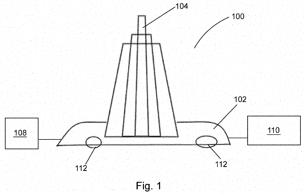
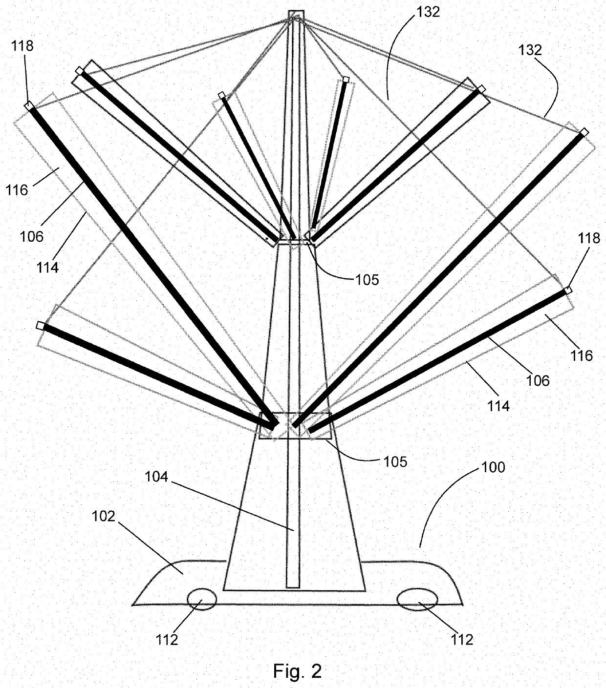
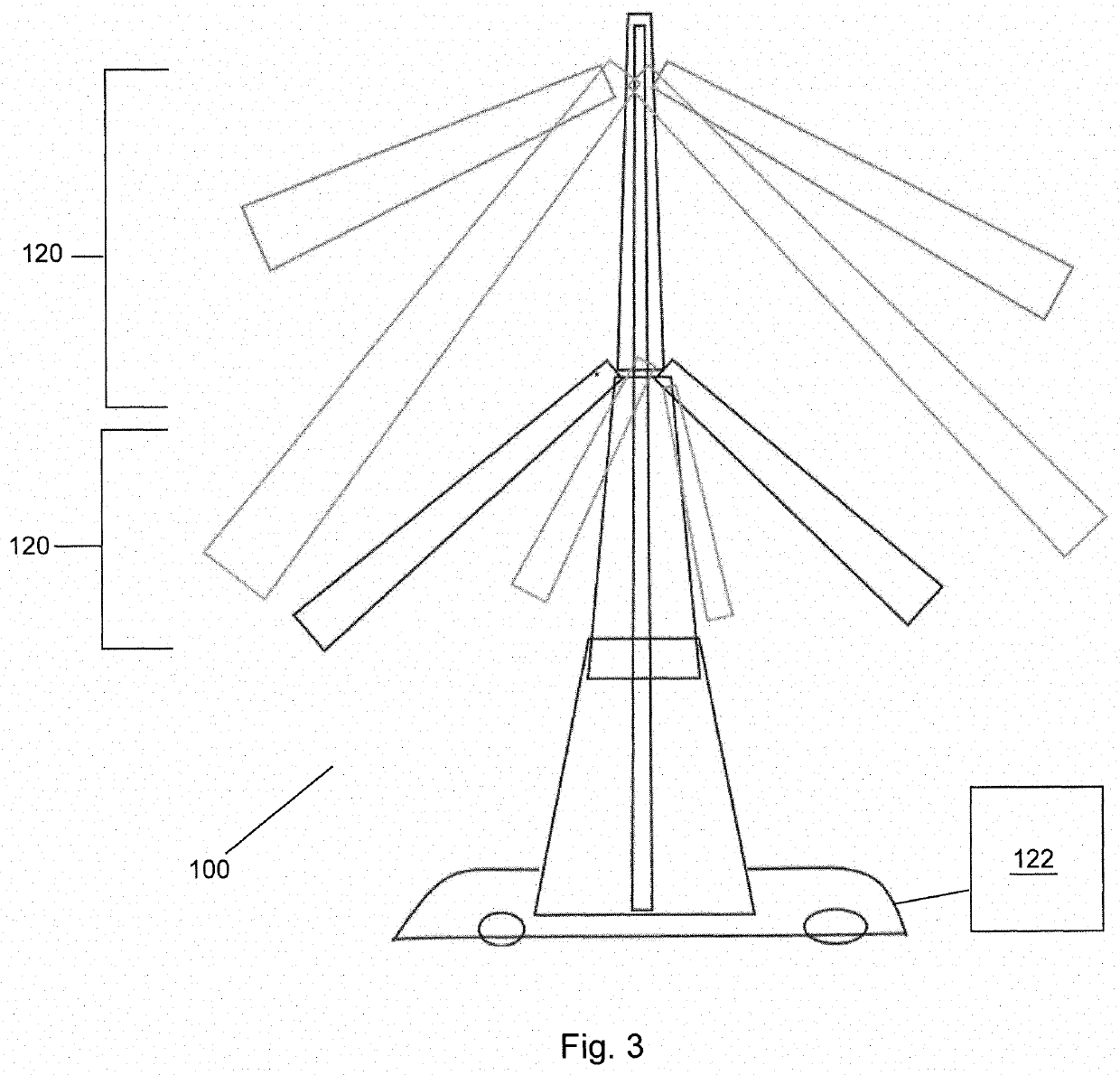
A generator pack for attachment to a vehicle, the generator pack comprising a housing, one or more pack layers located within the housing, and one or more turbine generators located within the housing for generating electrical power. Each of the pack layers comprises one or more photovoltaic panels for generating electrical power from light. Each of the turbine generators comprises a shaft, a plurality of blades attached to the shaft, wherein rotation of the blades causes rotation of the shaft, and a generator attached to the shaft, wherein the generator is configured to generate electrical power from rotation of the shaft. Movement of the vehicle effects movement of air against the blades, and the movement of air against the blades effects rotation of the blades and the shaft. The generator pack is configured to transmit electrical power from the pack layers and the turbine generators to the vehicle.

Description

CROSS-REFERENCE TO RELATED APPLICATIONS[0001]The present application is a Continuation-In-Part of U.S. patent application Ser. No. 17 / 416,025, filed on Jun. 18, 2021, which is a 371 of PCT Application Ser. No. PCT / CA2019 / 000173, filed on Dec. 20, 2019, which claims the benefit of U.S. Provisional Application Ser. No. 62 / 782,936, filed on Dec. 20, 2018, all of which are herein incorporated by reference for completeness of disclosure.BACKGROUND OF THE INVENTION[0002]In a few years, many in the world will be switching to electric vehicles, and this will lead to a major and serious surge in the need and demand for electrical energy. In addition, California's new energy code mandates solar panels on roofs of all new building by 2020, which will have an effect on the design and aesthetics of buildings to a certain extent.[0003]Currently, solar farms are being built in an attempt to replace or supplement the power generated using conventional, traditional power stations, but these farms ar...

Claims


Application Information

Patent Timeline
IPC IPC(8): H02S10/12H02S30/20H02S10/40H02K7/18B60L53/52B60L53/51F03D9/25F03D9/00
CPCH02S10/12H02S30/20H02S10/40H02K7/183H02S20/26B60L53/51F03D9/25F03D9/007B60L53/52Y02E10/50Y02E10/72F03D9/32F05B2240/941Y02T10/70Y02T10/7072Y02T90/12B60L8/003B60L8/006B60L2200/32F05B2220/708F05B2220/706
Inventor PAULUS, ANTOINE MARCEL
Owner PAULUS ANTOINE MARCEL
Learn More