Linear Actuator

Pending Publication Date: 2022-05-19
RELIANCE RG LTD
View PDF0 Cites 0 Cited by
  • Summary
  • Abstract
  • Description
  • Claims
  • Application Information

AI Technical Summary

Benefits of technology

The present invention is a linear actuator that can be combined with other such actuators in a compact and space-saving way. The actuator has a unique design that allows for interlocking with other actuators, ensuring that the shafts of the actuators have a fixed pitch when placed in a line along the assembly. The actuator can be operated individually or as part of an assembly, and can be screened from stray liquid and particulate solids. The actuator can be combined with other actuators using a mechanically positive or non-positive drive transmission. The actuator is designed with a worm wheel and worm interposed between the motor and the transmission, allowing for a simple means of step-down of motor output speed and blocking reverse driving.

Problems solved by technology

Formation of an assembly in this way is not compatible with achieving optimum compactness of an assembly, if this should be a requirement.
Such a pipetting machine may satisfactorily achieve its purpose in practice, but may be a relatively bulky construction of ad hoc design with significant limitations on flexibility and adaptability.

Method used


Image

  • Linear Actuator
  • Linear Actuator

Examples


Embodiment Construction

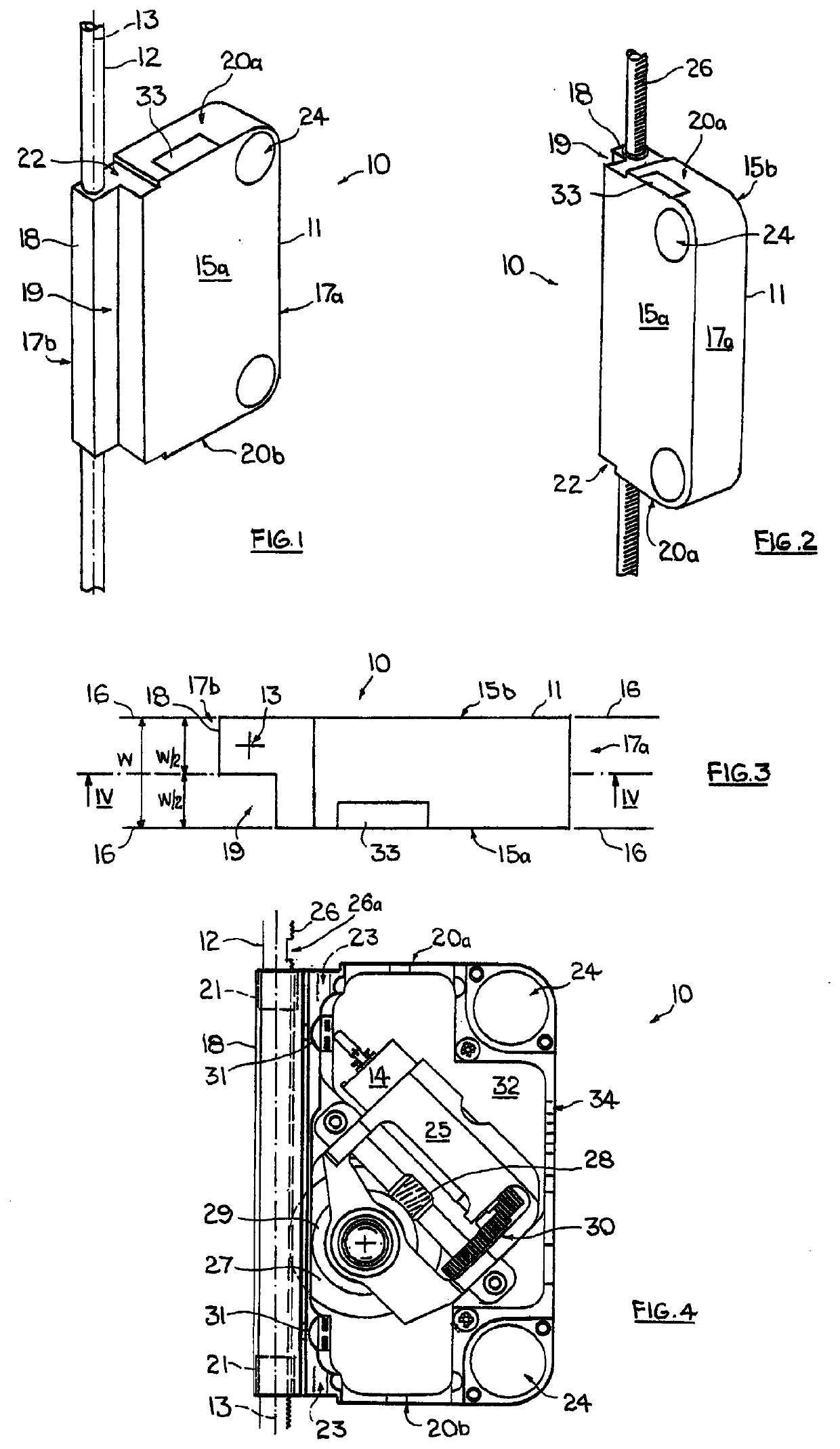
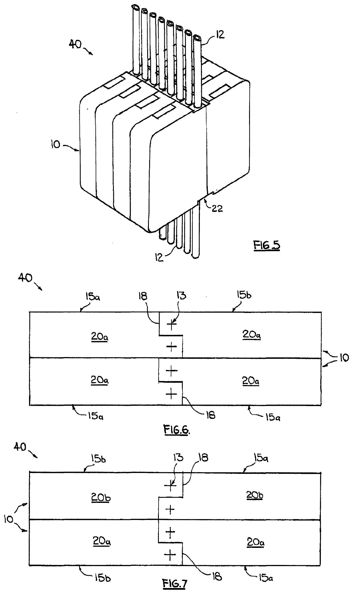
[0033]Referring now to the drawings there is shown a linear actuator 10 for use in forming a modular assembly 40 (FIGS. 5 to 7) of such actuators, the actuator comprising an actuator body 11, a shaft 12 guided by the body to be displaceable relative thereto in the sense of the longitudinal axis 13 of the shaft, and a speed-controllable, reversible-drive electric motor 14 (FIG. 4) enclosed in and supported by the body and operable to axially displace the shaft in two mutually opposite directions. In the actuator orientation shown in the drawings, those directions are vertically up and down, thus along a Z-axis, but the directions can be in any sense depending on the selected actuator orientation.

[0034]The body 11 is of substantially parallelopipedonal form with, in particular, two mutually opposite planar sides 15a and 15b which form major faces of the body and respectively lie in two substantially parallel spaced-apart planes 16, each plane representing a reference or contact plane ...


PUM


Abstract

A linear actuator (10) for use in a modular assembly of such actuators comprises an actuator body (11), a shaft (12) guided by the body to be displaceable relative thereto in the sense of tlte longitudinal axis (13) of the shaft and a drive motor enclosed in the body and operable to axially displace the shaft relative to the body in two mutually opposite directions. The body has two mutually opposite sides (15a, 15b) respectively lying in two substantial parallel spaced-apart planes, which each represent a reference plane for positioning the body side-by-side with the body of another such actuator, and a further side (17b) connecting the two mutually opposite sides and stepped to form a projection (18) receiving the shaft (12) with the axis (13) parallel to the two planes and a rebate (19) beside the projection to permit the body to interlock with the body of another such actuator at that further side. The projection (18) and rebate (19) are of substantially the same width in the sense of the spacing of the two planes and the shaft (12) is disposed substantially centrally of the projection (18) so that when the body (11) is interlocked with that of another such actuator the pitch of the shaft axes (13) is equal to that width.

Description

CROSS REFERENCE TO RELATED APPLICATIONS[0001]This application is a national stage entry of PCT / GB2020 / 000021, filed on Feb. 25, 2020 and currently pending, which claims priority to Great Britain patent application No. 1902567.5, filed on Feb. 26, 2019 and currently pending.FIELD OF THE INVENTION[0002]The present invention relates to a linear actuator and has particular reference to a linear actuator suitable for use in the creation of a modular assembly of such actuators. The invention further relates to an assembly of the actuators and to a machine incorporating the assembly.BACKGROUND OF THE INVENTION[0003]Linear actuators, that is to say drive units generating linear as opposed to rotary motion, exist in a great variety of forms and are employed for an equally diverse range of tasks. In most applications, such actuators are used individually and in general are not designed to be combined into assemblies, for which there may be a need only in specific circumstances. When there is ...

Claims


Application Information

Patent Timeline
IPC IPC(8): B01L3/02H02K7/07H02K7/116H02K11/22G01N35/10
CPCB01L3/0282H02K7/07H02K7/1166H02K11/22G01N35/1072G01N35/1011G01N2035/1076B01L2200/028B01L2200/0605B01L2300/0609B01L2300/0663B01L2400/0478B01L2200/026F16H19/04F16H57/033F16H2057/0335F16H2057/02069B01L3/0227B01L3/5085H02K7/081H02K7/06B01L3/02B01L3/0289G01N35/10H02K5/04
Inventor HORLER, GREGORY DOUGLASHEW, CHRISTOPHER MICHAEL
Owner RELIANCE RG LTD
Why Eureka
Try Eureka