Scintillator plate, method for manufacturing scintillator plate, and radiation detection apparatus

a technology of scintillator and scintillator plate, which is applied in the direction of radiation measurement, instruments, luminescent compositions, etc., can solve the problems of scintillator resolution deterioration, and achieve the effect of improving the resolution of the scintillator and suppressing light scattering

Active Publication Date: 2022-05-19
CANON KK
View PDF4 Cites 0 Cited by
  • Summary
  • Abstract
  • Description
  • Claims
  • Application Information

AI Technical Summary

Benefits of technology

[0006]The present disclosure was realized to address such a disadvantage and provides a technology useful to suppress light scattering between columnar crystals from occurring and to improve resolution of a scintillator.

Problems solved by technology

Regarding the technology disclosed in Japanese Patent Laid-Open No. 2019-2801, there is a disadvantage of deterioration in resolution of the scintillator due to an occurrence of light scattering between crystals since crystals formed in an initial stage of film formation are not sufficiently separated from each other.

Method used


Image

  • Scintillator plate, method for manufacturing scintillator plate, and radiation detection apparatus
  • Scintillator plate, method for manufacturing scintillator plate, and radiation detection apparatus
  • Scintillator plate, method for manufacturing scintillator plate, and radiation detection apparatus

Examples


example 1

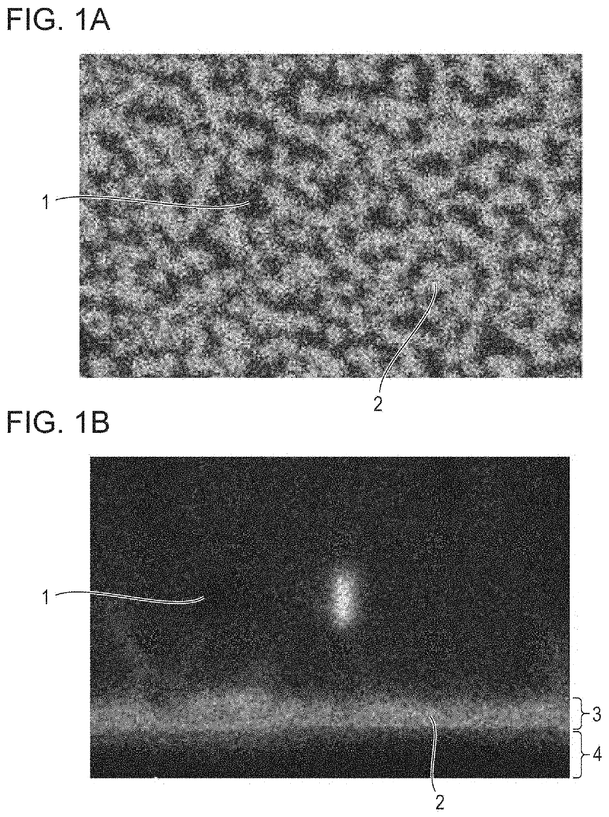
[0063]In the present example, the vacuum vapor deposition apparatus illustrated in FIG. 7 was used, and a deposited film having a columnar crystal structure in which the base material was CsI, the additive material was CuI, and the activating agent was TlI was formed.

[0064]The material supply source 71a was filled with a vapor deposition raw material 72a in which 0.3% by weight of CuI was mixed into CsI. In addition, the material supply source 71b was filled with CuI serving as a vapor deposition raw material 72b.

[0065]Further, the material supply source 71c was filled with TlI serving as a vapor deposition raw material 72c. The substrate 4 was set on the deposition surface 77. A silicon substrate on which an aluminum reflection layer having a thickness of 100 nm and silicon dioxide having a thickness of 50 nm were stacked was used as the substrate 4 in the same manner as in the comparative example.

[0066]The interior of the vapor deposition apparatus was evacuated to 0.01 Pa or les...

example 2

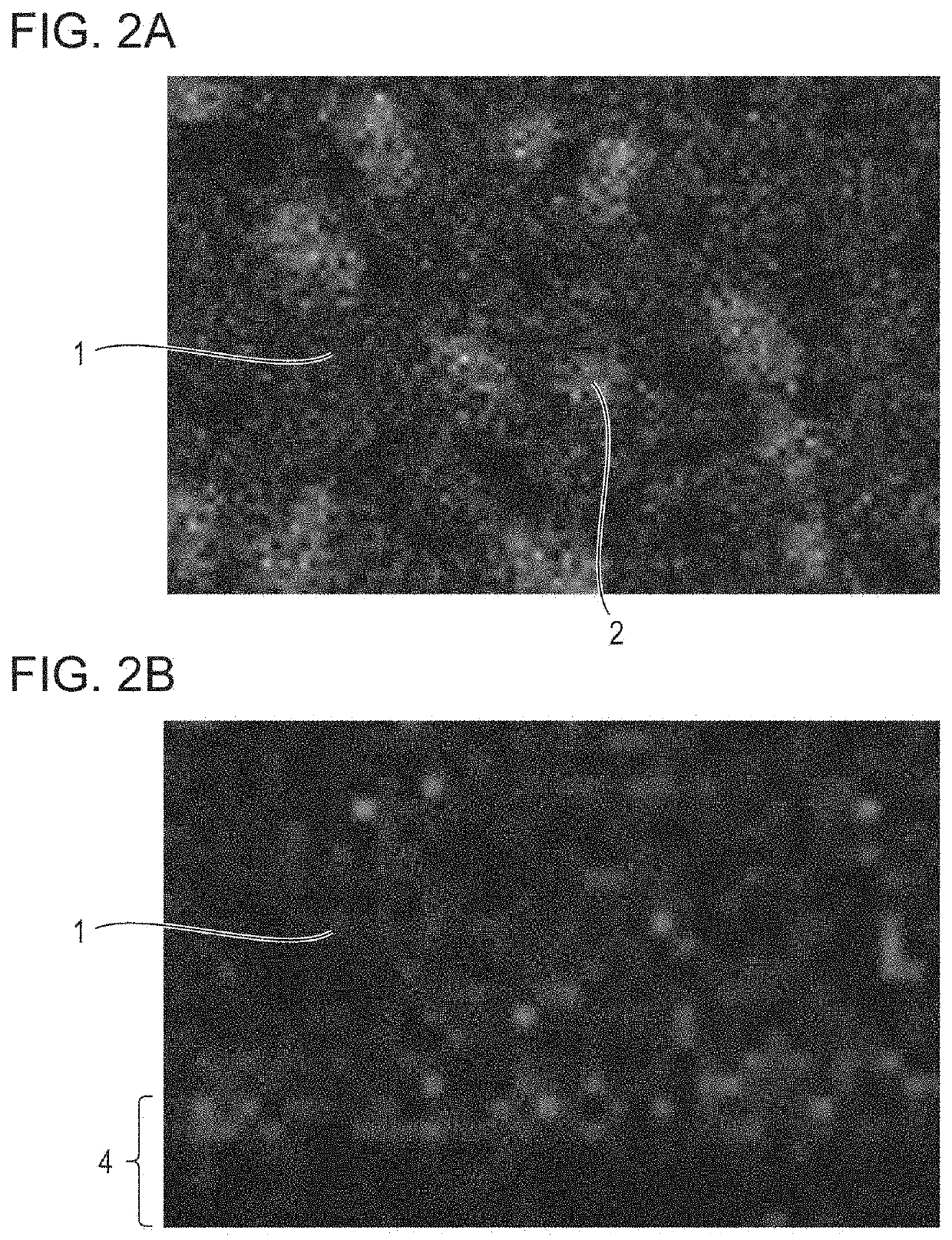
[0070]In the present example, the vacuum vapor deposition apparatus illustrated in FIG. 7 was used, and a deposited film having a columnar crystal structure in which the base material was CsI, the additive material was CuI, and the activating agent was TlI was formed.

[0071]The material supply source 71a was filled with CsI serving as a vapor deposition raw material 72a. In addition, the material supply source 71b was filled with CuI serving as a vapor deposition raw material 72b. Further, the material supply source 71c was filled with TlI serving as a vapor deposition raw material 72c. The substrate 4 was set on the deposition surface 77. The incident angle of the vapor particles from the material supply source 71a of CsI on the deposition surface 77 was set to be 60 degrees. A silicon substrate on which an aluminum reflection layer having a thickness of 100 nm and silicon dioxide having a thickness of 50 nm were stacked was used as the substrate 4 in the same manner as in the compa...


PUM

PropertyMeasurementUnit
thicknessaaaaaaaaaa
thicknessaaaaaaaaaa
lengthaaaaaaaaaa

Abstract

A layer in which a primary phase composed of a columnar crystal material and a secondary phase composed of a material different from the primary phase are phase-separated being included as a base for forming a columnar crystal of scintillator plate improves separation of columnar crystals from each other and suppresses light scattering from occurring so as to realize a scintillator having high resolution.

Description

BACKGROUND OF THE INVENTIONField of the Invention[0001]The present disclosure relates to a scintillator plate, a method for manufacturing a scintillator plate, and a radiation detection apparatus.Description of the Related Art[0002]Regarding a flat-panel detector (hereafter referred to as FPD) used for radiographic imaging in a medical field and the like, there is an indirect conversion FPD which converts radiation passed through an object to light by using a scintillator (radiation detection material) and detects the light emitted from the scintillator with a light-receiving element. In the scintillator to convert radiation to light, a columnar crystal group of an alkali metal halide such as cesium iodide is used to efficiently transfer the emitted light to a light-receiving element. In the columnar crystal group, gaps are formed between each of columnar crystals, and total reflection of the light is repeated in the crystal due to a difference in the refractive index between the cr...

Claims


Application Information

Patent Timeline
Patent Type & Authority Applications(United States)
IPC IPC(8): C09K11/62G01T1/202G01T1/20
CPCC09K11/628G01T1/2018G01T1/202
Inventor OIKE, TOMOYUKI
Owner CANON KK
Why Eureka
Try Eureka