
Oxidation heat treatment oven and method for manufacturing oxidized fiber bundle and carbon fiber bundle

Pending Publication Date: 2022-05-26
TORAY IND INC
View PDF0 Cites 0 Cited by
  • Summary
  • Abstract
  • Description
  • Claims
  • Application Information

AI Technical Summary

Benefits of technology

The present invention provides a method for efficiently producing oxidized fiber bundles and carbon fiber bundles with homogeneous physical properties and high quality without operational trouble. This is achieved by uniformizing the flow speed distribution of hot air in the vicinity of the blowout surface of a hot air supply nozzle. This technique eliminates the need for a separate member to control the air flow direction, reducing the risk of runaway reactions and ensuring uniform heat removal from the fiber bundle.

Problems solved by technology

Therefore, in the space sandwiched between the nozzles where the fiber bundle travels, the space in which hot air does not flow becomes large, and the risk of occurrence of runaway reaction caused by insufficient heat removal for the fiber bundle in which an exothermic reaction occurs is increased.
According to the findings of the present inventors, the most important factor for the swing of a fiber bundle caused by air speed unevenness is the air speed distribution in the vicinity of a nozzle blowout surface, and this point is not sufficiently studied in the prior art documents.

Method used


Image

  • Oxidation heat treatment oven and method for manufacturing oxidized fiber bundle and carbon fiber bundle
  • Oxidation heat treatment oven and method for manufacturing oxidized fiber bundle and carbon fiber bundle
  • Oxidation heat treatment oven and method for manufacturing oxidized fiber bundle and carbon fiber bundle

Examples


example 1

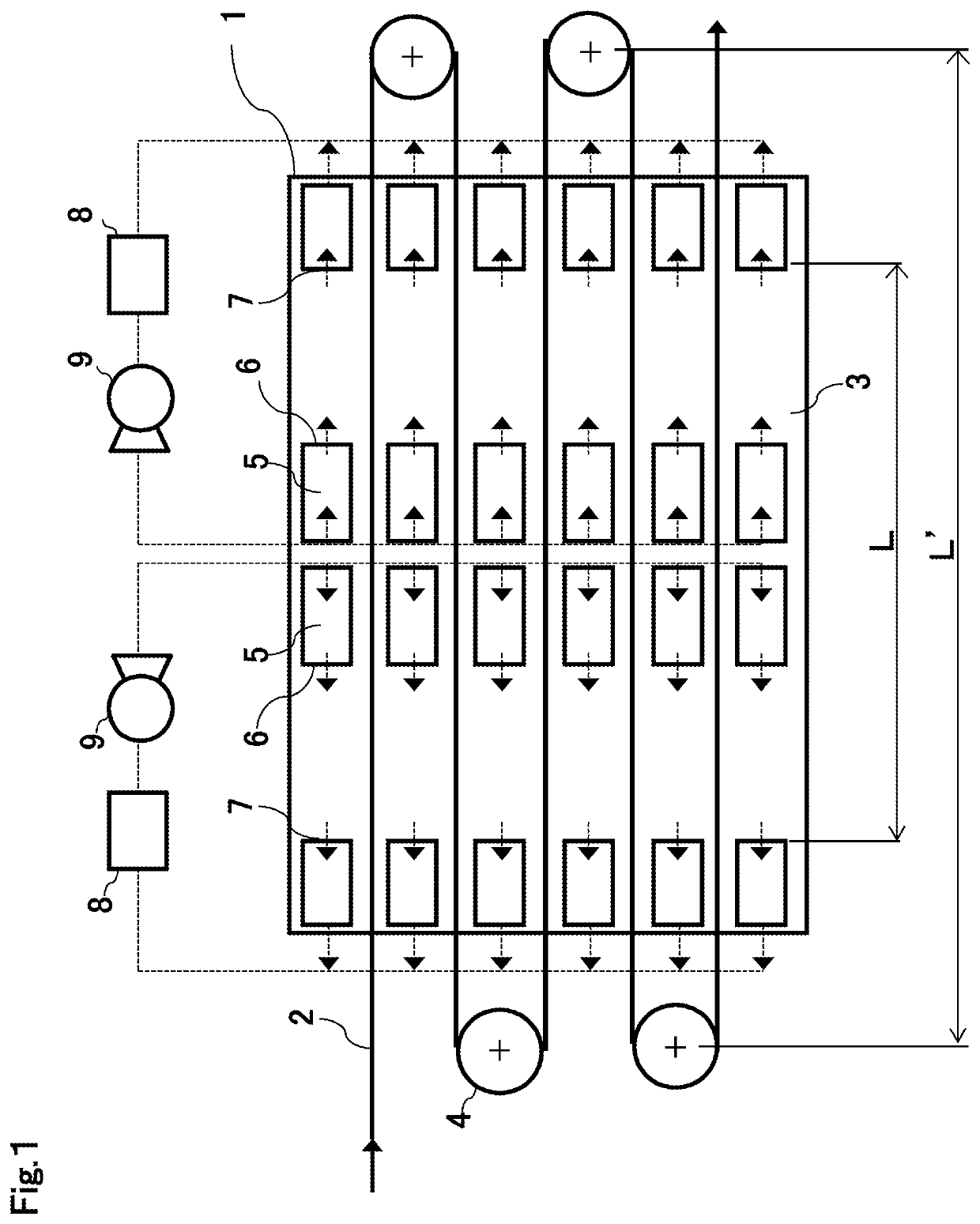
[0084]FIG. 1 is a schematic configuration diagram showing an example when the heat treatment oven according to an embodiment of the present invention is used as an oxidation oven for carbon fiber manufacturing. At centers between the guide rollers 4 on both sides of the oxidation oven 1, the hot air supply nozzles 5 are installed above and below the acrylic fiber bundle 2 traveling in the oxidation oven 1. The hot air supply nozzle 5 was provided with the hot air supply port 6 in a traveling direction of the fiber bundle or in a direction opposite to the traveling direction of the fiber bundle.

[0085]For the acrylic fiber bundle 2 that travels in the oven, 100 fiber bundles each composed of 20,000 single fibers having a single fiber fineness of 0.11 tex were aligned and heat-treated in the oxidation oven 1 to obtain an oxidized fiber bundle. The horizontal distance L′ between the guide rollers 4 on both sides of the heat treatment chamber 3 of the oxidation oven 1 was 15 m, the guide...

example 2

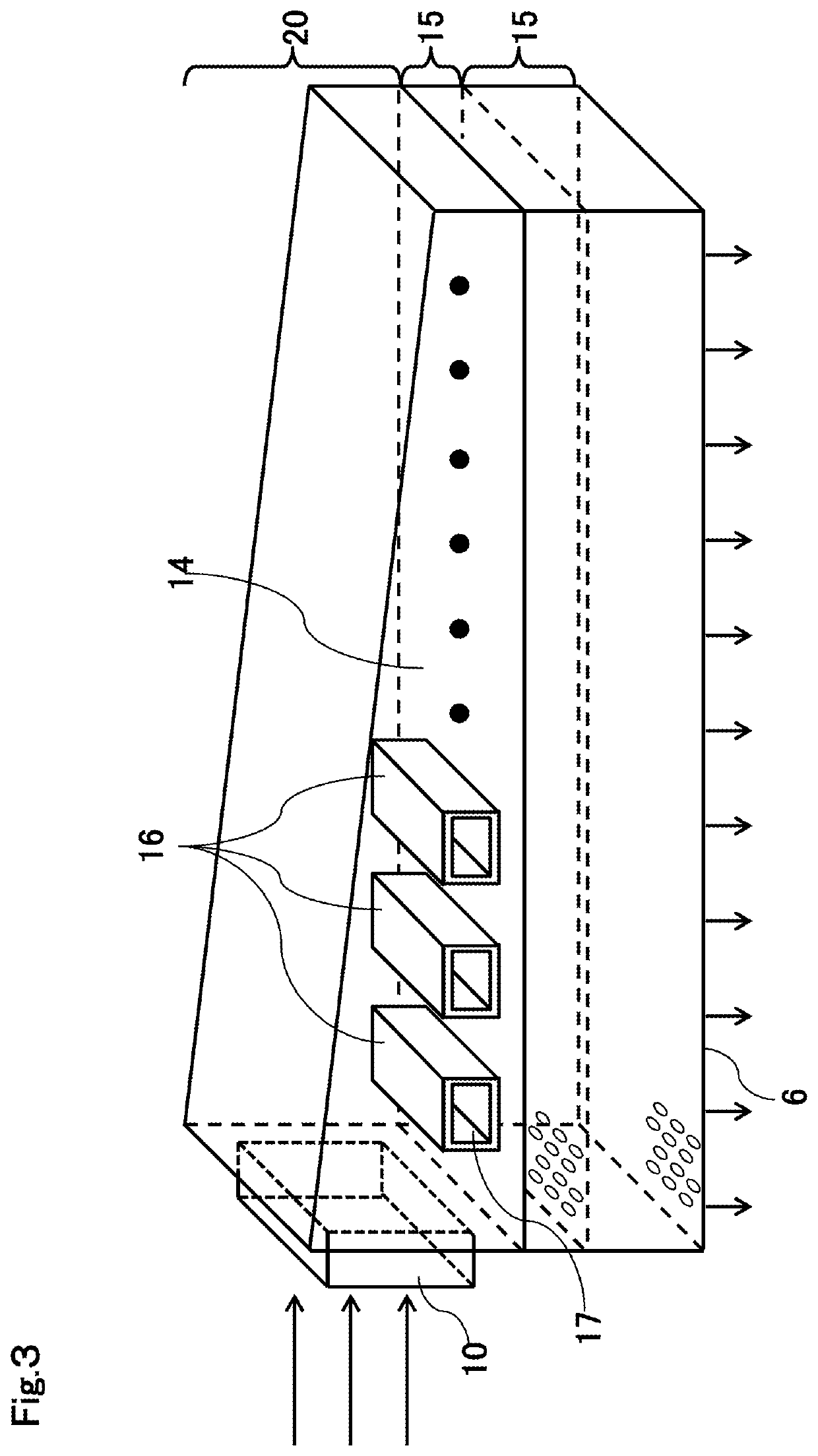
[0089]The procedure similar to that of Example 1 was carried out except that, in the hot air supply nozzle 5 shown in FIGS. 3, 4, and 5, the internal angle θ was 90°, and the interval S between the adjacent cylindrical bodies was reduced to 5 mm. In this case, the air speed variation was 8.6%. Under the above conditions, fiber mixing, fiber bundle breakage, or the like due to contact between the fiber bundles did not occur at all during the oxidation treatment of the acryl fiber bundle, and an oxidized fiber bundle was acquired with extremely good process stability. In addition, the obtained oxidized fiber bundle and carbon fiber bundle were visually checked, and the result showed that the quality was extremely good without fuzz or the like.

example 3

[0090]The procedure similar to that of Example 2 was carried out except that an interval S between adjacent cylindrical bodies was 0 mm. In other words, in this configuration, all the cylindrical bodies are connected to the partition plate so that the cylindrical bodies are in contact with each other, and the gas flow hole 18 is a slit extending along the longitudinal axis of the nozzle. In this case, the air speed variation was 8.2%. Under the above conditions, fiber mixing, fiber bundle breakage, or the like due to contact between the fiber bundles did not occur at all during the oxidation treatment of the acryl fiber bundle, and an oxidized fiber bundle was acquired with extremely good process stability. In addition, the obtained oxidized fiber bundle and carbon fiber bundle were visually checked, and the result showed that the quality was extremely good without fuzz or the like.


PUM

PropertyMeasurementUnit
Temperatureaaaaaaaaaa
Angleaaaaaaaaaa

Abstract

There is provided an oxidation heat treatment oven including a heat treatment chamber configured to heat-treat a fiber bundle that is an aligned acrylic fiber bundle in an oxidizing atmosphere to form an oxidized fiber bundle; a slit-shaped opening configured to take the fiber bundle in and out of the heat treatment chamber; guide rollers installed at both ends of the heat treatment chamber and configured to turn the fiber bundle back; a hot air supply nozzle that has a longitudinal axis along the width of the fiber bundle traveling and that blows out hot air, in a direction substantially parallel to a traveling direction of the fiber bundle, above and / or below the fiber bundle traveling in the heat treatment chamber; and a suction nozzle configured to suck the hot air blown out from the hot air supply nozzle, in which the hot air supply nozzle satisfies disclosed conditions (1) to (3).

Description

CROSS REFERENCE TO RELATED APPLICATIONS[0001]This is the U.S. National Phase application of PCT / JP2020 / 003057, filed Jan. 29, 2020, which claims priority to Japanese Patent Application No. 2019-050792, filed Mar. 19, 2019 the disclosures of each of these applications being incorporated herein by reference in their entireties for all purposes.FIELD OF THE INVENTION[0002]The present invention relates to an apparatus for manufacturing an oxidized fiber bundle. More specifically, the present invention relates to an apparatus for manufacturing an oxidized fiber bundle, the apparatus being capable of efficiently manufacturing an oxidized fiber bundle with homogeneous physical properties and high quality without operational trouble.BACKGROUND OF THE INVENTION[0003]Since carbon fibers are excellent in specific strength, specific elastic modulus, heat resistance, and chemical resistance, they are useful as reinforcing materials for various materials and are used in a wide range of fields suc...

Claims


Application Information

Patent Timeline
IPC IPC(8): D01F9/32D01F9/21
CPCD01F9/328D01F9/21D01F9/22D01F9/225D01F9/32
Inventor HOSOTANI, NAOTOYAMAMOTO, TAKUGONDO, KAZUYUKICHIEDA, SHIGEKINISHIKAWA, TORUNOMURA, FUMIYASU
Owner TORAY IND INC
Features
  • Generate Ideas
  • Intellectual Property
  • Life Sciences
  • Materials
  • Tech Scout
  • Unparalleled Data Quality
  • Higher Quality Content
  • 60% Fewer Hallucinations
Learn More