Method and apparatus for milling a window in casing

a technology of casing and window, which is applied in the direction of earthwork drilling, well accessories, borehole/well accessories, etc., can solve the problems of difficult milling operation, less predictable success, and difficult milling process, and achieve the effect of not significantly affecting the strength of tubing/casing

Pending Publication Date: 2022-06-02
CONOCOPHILLIPS CO
View PDF5 Cites 0 Cited by
  • Summary
  • Abstract
  • Description
  • Claims
  • Application Information

AI Technical Summary

Benefits of technology

[0012]The advantages of this two stage process are that the initial, risky phase of the operation can be done without the expense of committing to deploying a drilling rig and associated equipment for a coil tubing or drill pipe based operation. Only when it is apparent that the job is likely to succeed is it necessary to commit to this cost. If the wireline milling tool is only required to cut a ledge, or notch (relatively small aperture) in the casing, then the stroki...

Problems solved by technology

The milling operation can be difficult and the process is not always successful.
High grade casing may be employed, e.g. Q-125 grade casing commonly used in the Greater Ekofisk Area (GEA) of the North Sea, which can make the milling process harder and success less predictable.
Since the casing supporting the gripping apparatus and milling tool is itself being milled away in the proce...

Method used


Image

  • Method and apparatus for milling a window in casing

Examples


Embodiment Construction

[0031]Turning now to the detailed description of the preferred arrangement or arrangements of the present invention, it should be understood that the inventive features and concepts may be manifested in other arrangements and that the scope of the invention is not limited to the embodiments described or illustrated. The scope of the invention is intended only to be limited by the scope of the claims that follow.

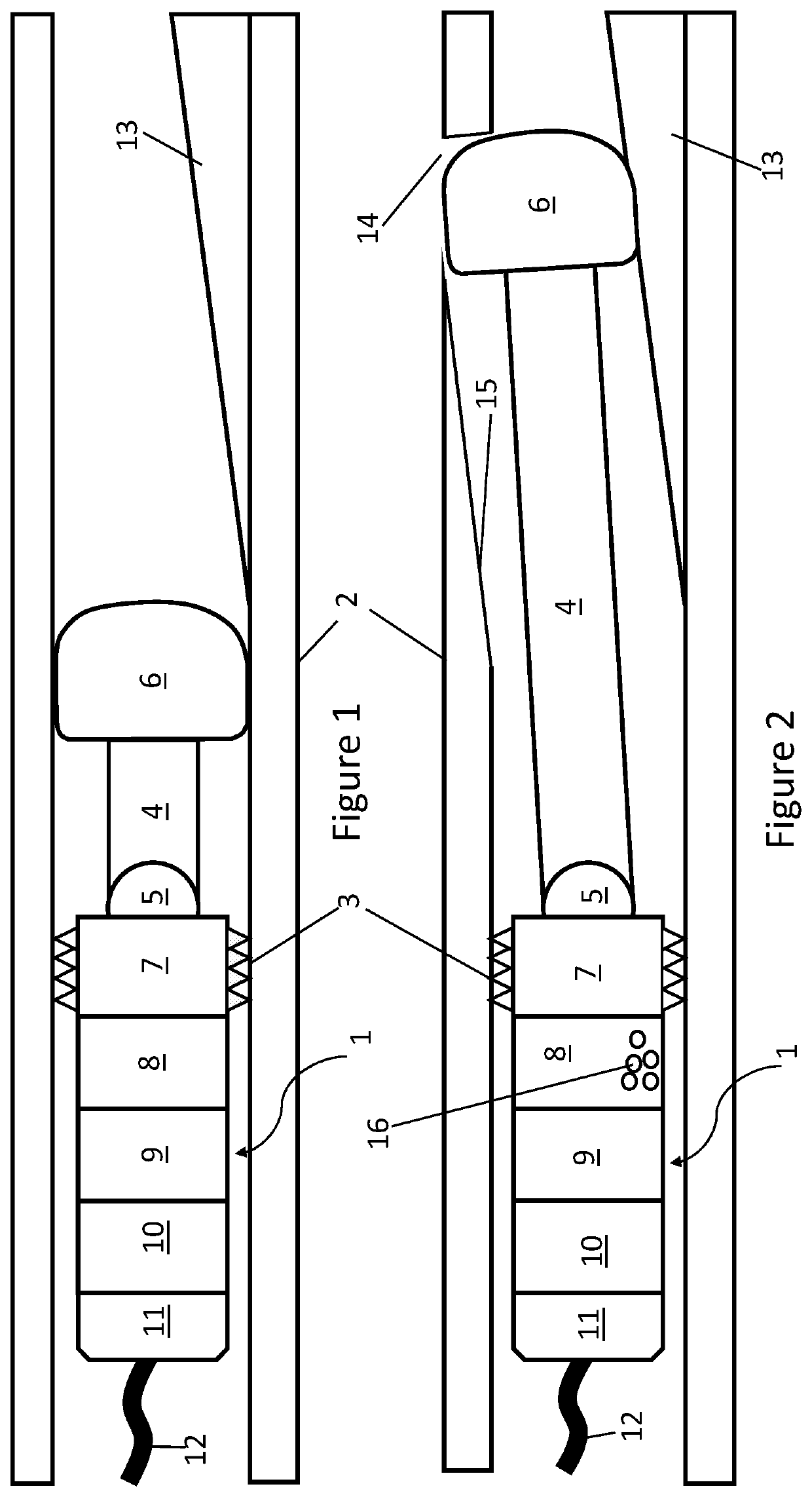
[0032]FIG. 1 shows a milling tool in accordance with the invention. The drawing is not to scale, and the aspect ratios of the various components may have been shown incorrectly for the sake of clarity. The terms “proximal” and “distal” are used to describe the location of features of the tool, and these terms are used with respect to the entrance to the well, i.e. the surface.

[0033]The tool comprises a tool body 1 which is shown anchored in casing 2 by means of retractable gripping elements 3. At the distal end of the tool is an actuator arm 4 mounted to the tool body 1 via a...


PUM


Abstract

A process is described for milling a window in the casing (2) of an oil or gas producing well, for example in order to drill a lateral well branching off from the main well. A wireline milling tool is first used, in a relatively low cost operation, to create a small window (14) or notch in the casing (2). Provided a small window (14) or notch can be created successfully, an expensive heavy duty coil tubing milling operation can then be conducted to create the full window, some 4-6 feet in length. Previous attempts to create a full window using wireline tools have encountered difficulties due to there being no circulating drilling fluid to remove metal swarf and due to the need for the tool to be supported by casing during the milling operation, when the integrity of the casing is being compromised by drilling the window. The proposed wireline tool has an actuator (4) with relatively small stroke length and a relatively small container (8) to manage the swarf produced by the milling process. (FIG. 2).

Description

CROSS-REFERENCE TO RELATED APPLICATIONS[0001]This application is a non-provisional application which claims benefit under 35 USC § 119(e) to U.S. Provisional Application Ser. No. 63 / 120,612 filed Dec. 2, 2020, entitled “ METHOD AND APPARATUS FOR MILLING A WINDOW IN CASING,” which is incorporated herein in its entirety.STATEMENT REGARDING FEDERALLY SPONSORED RESEARCH[0002]None.FIELD OF THE INVENTION[0003]This invention relates to the milling of a window in the casing of an oil or gas well, for example in order to allow for drilling a sidetrack well.BACKGROUND OF THE INVENTION[0004]Prior to sidetracking a well, a window is cut into the existing casing to create a point of departure. For thru-tubing drilling, the process of milling the window is normally carried out using a milling tool run into the well on coil tubing through the existing production tubing. The milling operation can be difficult and the process is not always successful.[0005]For offshore operations, coiled tubing oper...

Claims


Application Information

Patent Timeline
IPC IPC(8): E21B29/06E21B29/04E21B29/12
CPCE21B29/06E21B29/12E21B29/04
Inventor MARIBU, KENNETHELLER, JOHN GARYRYAN
Owner CONOCOPHILLIPS CO
Why Eureka
Try Eureka