Supercharge Your Innovation With Domain-Expert AI Agents!

On-board bidirectional ac fast charger for electric vehicles

a fast charger and electric vehicle technology, applied in the direction of battery/fuel cell propulsion, battery/cell control arrangement, transportation and packaging, etc., can solve the problems of electric vehicles that require a significant amount of power, electric vehicles that have had relatively slow adoption, and damage to on-board components, so as to improve the flexibility of potential grid connection, the effect of preventing damage to the on-board components and flexible operation

Active Publication Date: 2022-06-02
HAVELAAR CANADA IND R & D LAB LTD +1
View PDF2 Cites 0 Cited by
  • Summary
  • Abstract
  • Description
  • Claims
  • Application Information

AI Technical Summary

Benefits of technology

The solution provides a cost-effective, efficient, and flexible charging system that reduces component requirements, supports renewable energy sources, and enables the vehicle to act as a power source for grid support, enhancing the environmental impact and practicality of electric vehicles.

Problems solved by technology

Providing electric charging with power electronics can be challenging, especially with electrically powered portable objects, such as electric vehicles (EVs) or portable generators.
Electric vehicles require a significant amount of power for propulsion, control systems, entertainment systems, over a sustained period of time.
However, electric vehicles have had relatively slow adoption due to limitations relating to electric vehicle technology, especially in relation to energy storage and charging.
Chargers for electric vehicles are often very expensive as charging stations are implemented with bulky and heavy designs where dedicated electronics are required.
A challenge with interoperability occurs in relation to the waveform and / or frequency of the grid current, and a technical objective is to use technical mechanisms to impose (e.g., regulate) the grid current such that it has a same (or significantly similar) waveshape and / or frequency as the grid voltage.
Other embodiments are possible, for example, diodes can be utilized rather than the current bi-directional two quadrant switches, but where diodes are utilized, the charger is not able to provide bi-directional charging and operates at unity power factor.

Method used


Image

  • On-board bidirectional ac fast charger for electric vehicles
  • On-board bidirectional ac fast charger for electric vehicles
  • On-board bidirectional ac fast charger for electric vehicles

Examples


Embodiment Construction

[0069]A typical on-board charger consists of a DC / AC stage and an isolated DC / DC stage connected to the AC grid. Alternatively, isolation can be provided through an off-board transformer. The isolated DC / DC stage is able to accommodate variations in battery voltage. Such an on-board charger is an additional component to a vehicle, which adds cost and weight to the vehicle that is un-used when the vehicle is in motion.

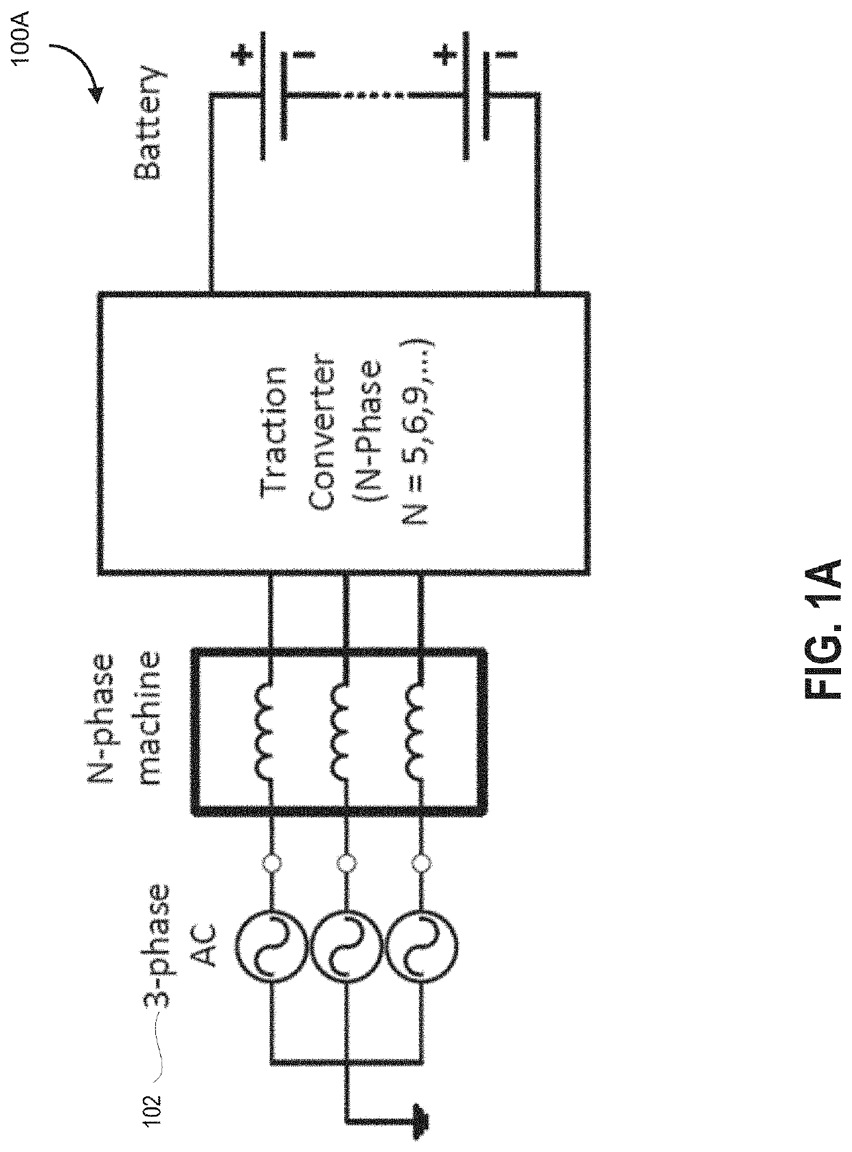
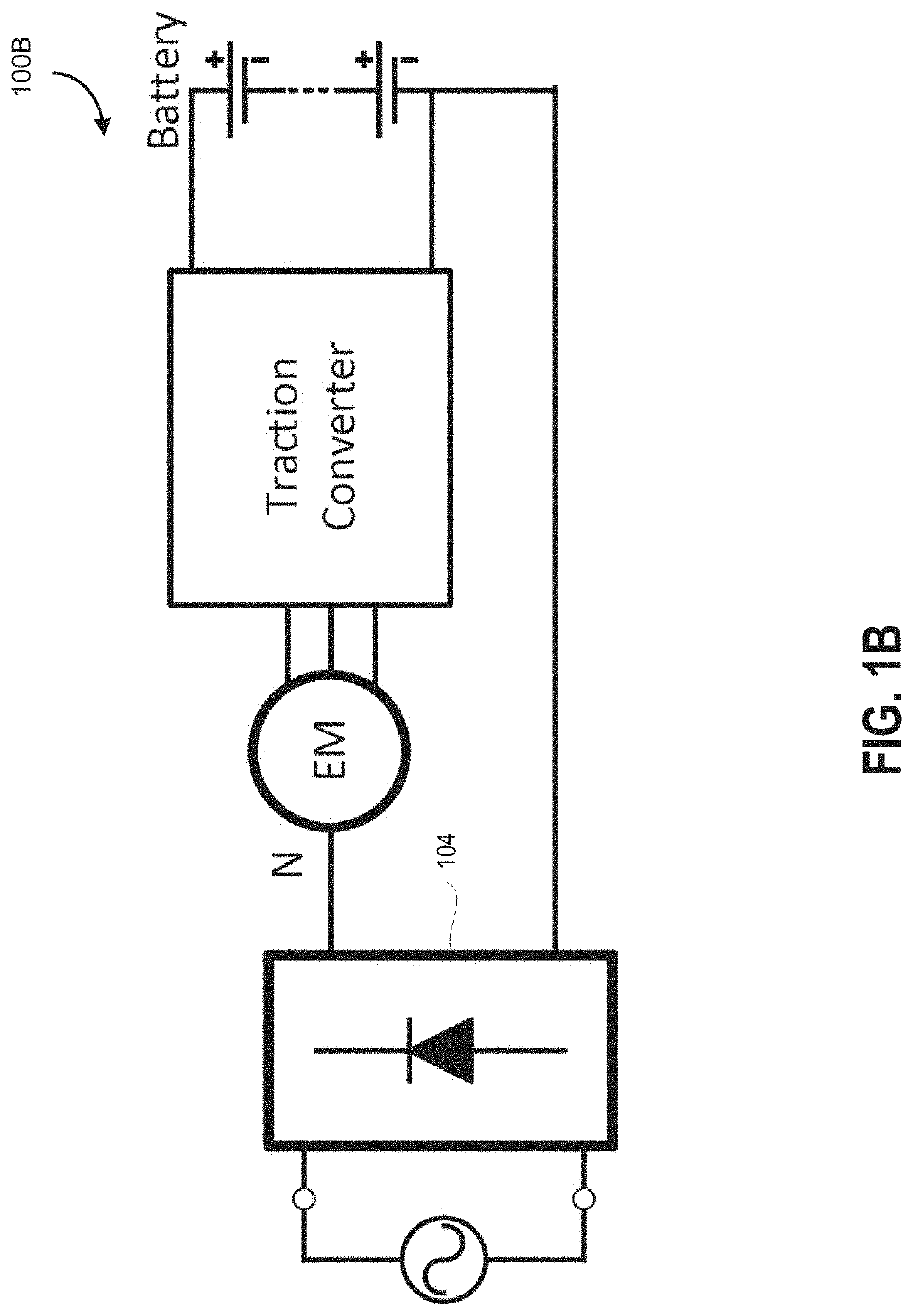
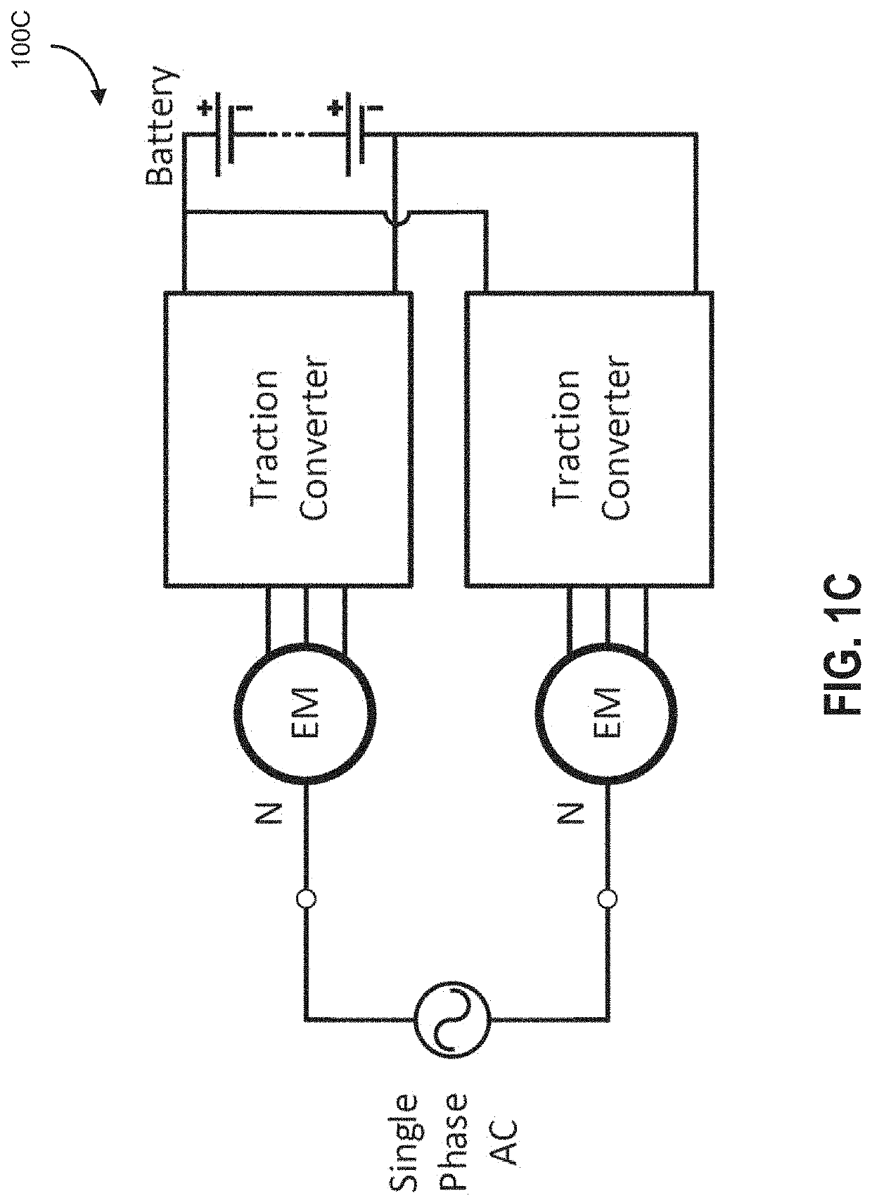
[0070]As described in some embodiments herein, an improved approach for utilizing existing magnetics (e.g., of the vehicle when it is not in motion) for providing fast-charging capabilities. The proposed converter of some embodiments is an on-board AC fast charger that advantageously utilizes the leakage inductance of the motor of an electric vehicle, enabling the charger to re-use magnetics of the motor for charging which conventionally would not be used when the vehicle is stationary. An additional switching stage (having one or more sets of switches) is provided. The...


PUM


Abstract

An electric vehicle fast charger and methods thereof are described, adapted for re-use of magnetic components of an electric vehicle having traction converters when the electric vehicle is stationary and connected to a power grid. A switching stage provided by one or more sets of switches is controlled complementarily with the switches of the traction converters to (i) provide inversion of a grid voltage and (ii) shape current of the grid current between the electric vehicle and the power grid to track a waveshape of the grid voltage. A single switching stage and a dual switching stage circuit are contemplated, along with switch controller circuits, and instruction sets for switch control. Variants provide for energy transfer to accommodate for energy imbalances between storage devices.

Description

CROSS-REFERENCE[0001]This application is a Continuation of U.S. application Ser. No. 16 / 755,831 filed on Apr. 13, 2020, which is a 371 Application of PCT Application No. PCT / CA2018 / 051292 filed on Oct. 12, 2018, which is a non-provisional of, and claims all benefit, including priority to, U.S. Application No. 62 / 572,120, filed Oct. 13, 2017, entitled “On-board bidirectional AC fast charger for electric vehicles”, incorporated herein by reference in its entirety.FIELD[0002]Some embodiments of the present disclosure generally relates to the field of power electronics, and more specifically, to charger technology for use with electric vehicles or other portable electronics.INTRODUCTION[0003]Providing electric charging with power electronics can be challenging, especially with electrically powered portable objects, such as electric vehicles (EVs) or portable generators. Electric vehicles require a significant amount of power for propulsion, control systems, entertainment systems, over a...

Claims


Application Information

Patent Timeline
Patent Type & Authority Applications(United States)
IPC IPC(8): H02J3/32H02J50/10B60L58/12B60L53/122
CPCH02J3/322B60L53/122B60L58/12H02J50/10H02J7/02B60L53/22B60L53/24B60L55/00H02J7/1423H02J7/24Y04S10/126Y02E60/00B60L53/14B60L53/12B60L50/60Y02T10/7072Y02T10/70Y02T90/14
Inventor LEHN, PETERSOONG, THEODOREGRAY, PHILIPPESEMSAR, SEPEHR
Owner HAVELAAR CANADA IND R & D LAB LTD
Features
  • R&D
  • Intellectual Property
  • Life Sciences
  • Materials
  • Tech Scout
  • Unparalleled Data Quality
  • Higher Quality Content
  • 60% Fewer Hallucinations
Learn More