Display with underlying decorative layer

a display and decorative layer technology, applied in the field of electronic displays, can solve the problems of black screen undesired contrast with the visual aesthetics of the surrounding dashboard, difficult to achieve a truly seamless blending between the border and the display area, and poor image quality of the display, so as to reduce the visibility of the display module

Pending Publication Date: 2022-06-09
CORNING INC
View PDF0 Cites 2 Cited by
  • Summary
  • Abstract
  • Description
  • Claims
  • Application Information

AI Technical Summary

Benefits of technology

[0011]An assembly can include: a decorative layer and a transparent display module. The decorative layer can include a substrate panel. The transparent display module can be mounted to the decorative layer and include a glass substrate. The assembly can be configured such that when the display module is in an inactive state, the decorative layer is visible through the glass substrate. The glass substrate can include an optical coating or texture that modifies light transmittance and / or light reflectance in a manner that reduces visibility of the display module, causing an area within the display module to have an appearance that is similar to the decorative layer.

Problems solved by technology

The black screen may undesirably contrast with the visual aesthetics of the surrounding dashboard.
However, it is difficult to achieve a truly seamless blending between the border and display area.
Because display light passes through the metallic or textured surface before reaching a viewer, the display may exhibit poor image quality.

Method used


Image

  • Display with underlying decorative layer
  • Display with underlying decorative layer
  • Display with underlying decorative layer

Examples


Embodiment Construction

[0022]The present application discloses illustrative (i.e., example) embodiments. The claimed inventions are not limited to the illustrative embodiments. Therefore, many implementations of the claims will be different than the illustrative embodiments. Various modifications can be made to the claimed inventions without departing from the spirit and scope of the disclosure. The claims are intended to cover implementations with such modifications.

[0023]At times, the present application uses directional terms (e.g., front, back, top, bottom, left, right, etc.) to give the reader context when viewing the Figures. The claimed inventions, however, are not limited to the orientations shown in the Figures. Any absolute term (e.g., high, low, etc.) can be understood and disclosing a corresponding relative term (e.g., higher, lower, etc.).

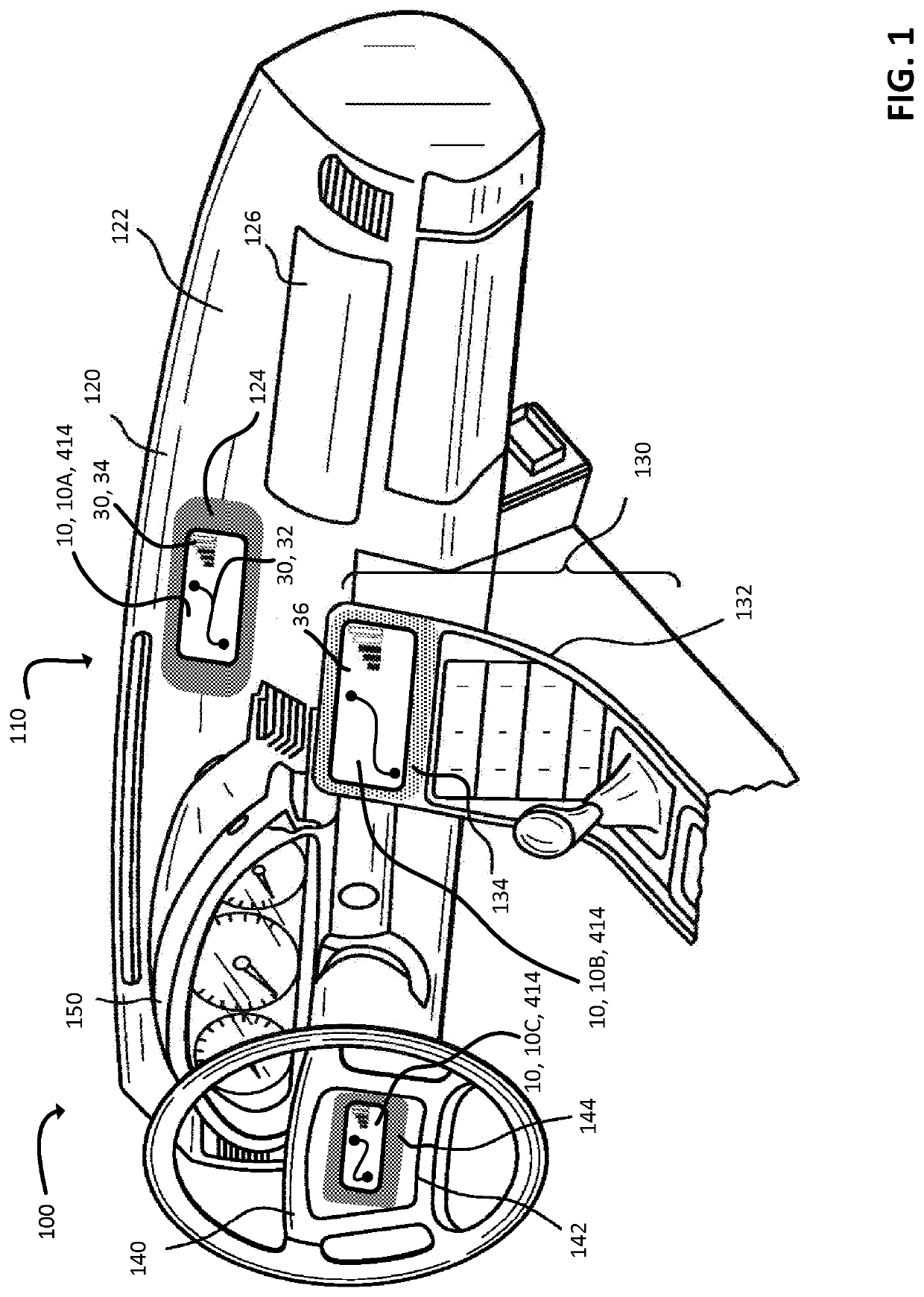
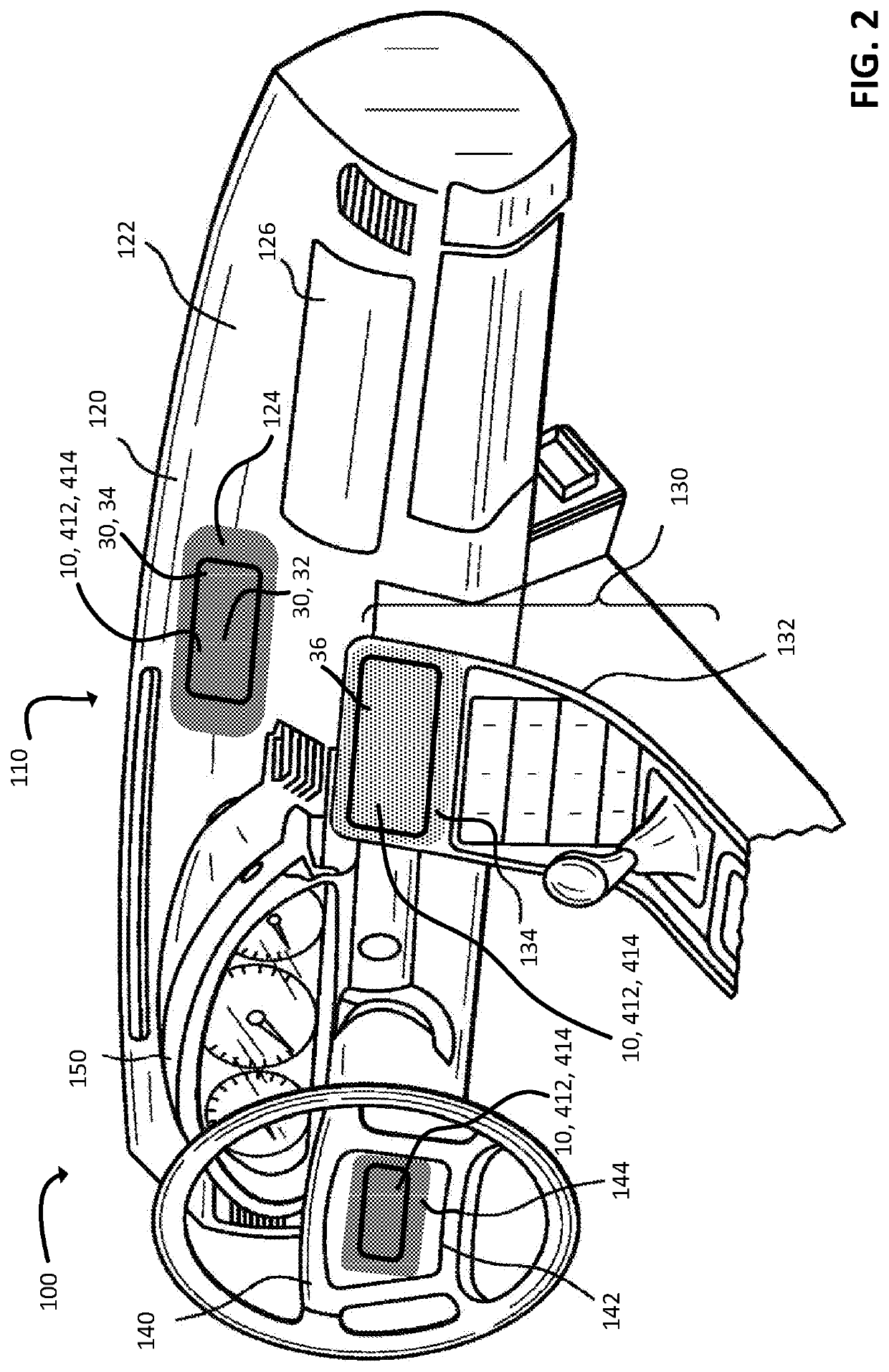
[0024]Referring to FIG. 1, a vehicle 100 (also called a system) can include a dashboard 110 (also called a support) for receiving inputs from a user (e.g., ...


PUM


Abstract

A system such as a vehicle, an appliance, or a mobile phone can include an assembly featuring a decorative layer and a transparent display module. The decorative layer can include ink applied to a substrate. The transparent display module can be mounted to the decorative layer and include an array of pixels disposed behind an outer cover glass. The assembly can be configured such that when the display module is in a first mode, the decorative layer is visible from the cover glass and through the pixel array.

Description

CROSS-REFERENCE TO RELATED APPLICATIONS[0001]This application claims the benefit of priority under 35 U.S.C. § 119 of U.S. Provisional Application Ser. No. 62 / 840,249 filed on Apr. 29, 2019 the content of which is relied upon and incorporated herein by reference in its entirety.BACKGROUNDField of the Disclosure[0002]Among other things, the present disclosure relates to an electronic display. The display can be located in a vehicle.Description of Related Art[0003]Vehicles can include a dashboard integrating one or more electronic displays such as liquid crystal displays (LCDs), organic light emitting diode (OLED) displays, waveguide displays, etc. When active, a display can present graphics for enabling user interaction with various vehicle systems. For example, a display can present graphics enabling user control of air conditioning, audio, autonomous driving, or telecommunications. When inactive, a display can present a black screen. The black screen may undesirably contrast with t...

Claims


Application Information

Patent Timeline
Patent Type & Authority Applications(United States)
IPC IPC(8): B60K37/02
CPCB60K37/02B60K2370/688B60K2370/39B60Y2200/11B60K2370/349B60K2370/23B60K2370/1523G02F1/133308G02F1/133509G02F2201/38G02F2201/58G02F1/133331
Inventor HART, SHANDON DEERIGGS, FRANK BROCK
Owner CORNING INC
Why Eureka
Try Eureka